Liquid crystal optical device configured to reduce polarization dependent loss and polarization mode dispersion

a liquid crystal optical device and polarization mode technology, applied in static indicating devices, non-linear optics, instruments, etc., can solve problems such as inequal intensities for each channel

Active Publication Date: 2010-12-02
II VI DELAWARE INC
View PDF2 Cites 23 Cited by
  • Summary
  • Abstract
  • Description
  • Claims
  • Application Information

AI Technical Summary

Benefits of technology

[0007]One of keys in reducing PDL and PMD in an LC-based optical switch is to minimize the differences in the optical paths traversed by the s- and p-polarized components. One or more embodiments of the present invention provide an LC-based optical device that is configured to reduce PDL and PMD and a method for reducing PDL and PMD in an LC-based optical device.
[0011]A method for compensating for PDL in an LC-based optical device having a birefringent displacer includes the steps of measuring the PDL of the input beam, rotating the birefringent displacer, and measuring the PDL of the input beam after rotation of the birefringent displacer. The steps of rotating and measuring may be carried out until the measured PDL is at a minimum. After the minimum PDL is found, the birefringent displacer is affixed to its mounting frame so that the angle formed by its front planar surface with respect to an optical path of the input beam can be maintained during operation.

Problems solved by technology

In practice, different wavelength channels of a WDM signal typically undergo asymmetrical losses as they travel through an optical communication system, resulting in unequal intensities for each channel.

Method used


Image

  • Liquid crystal optical device configured to reduce polarization dependent loss and polarization mode dispersion
  • Liquid crystal optical device configured to reduce polarization dependent loss and polarization mode dispersion
  • Liquid crystal optical device configured to reduce polarization dependent loss and polarization mode dispersion

Examples


Embodiment Construction

[0021]One or more embodiments of the present invention provide an LC-based optical device that is configured to reduce PDL and PMD and a method for reducing PDL and PMD in an LC-based optical device. The LC-based optical device may be a wavelength selective switch (WSS) and the present invention will be described below in the context of a WSS. However, the present invention is applicable to other types of LC-based optical devices, such as a reconfigurable optical add-drop multiplexer (ROADM).

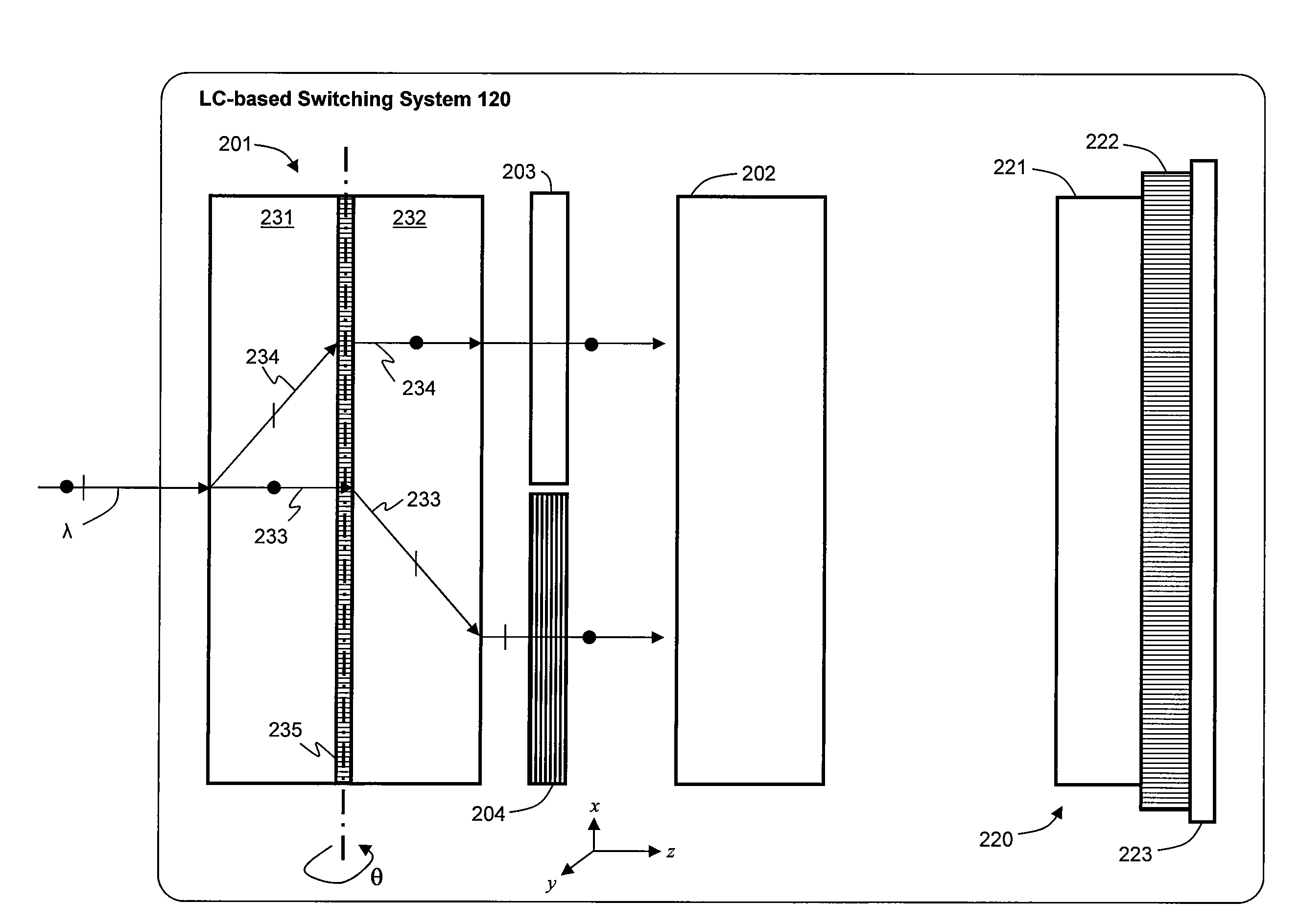
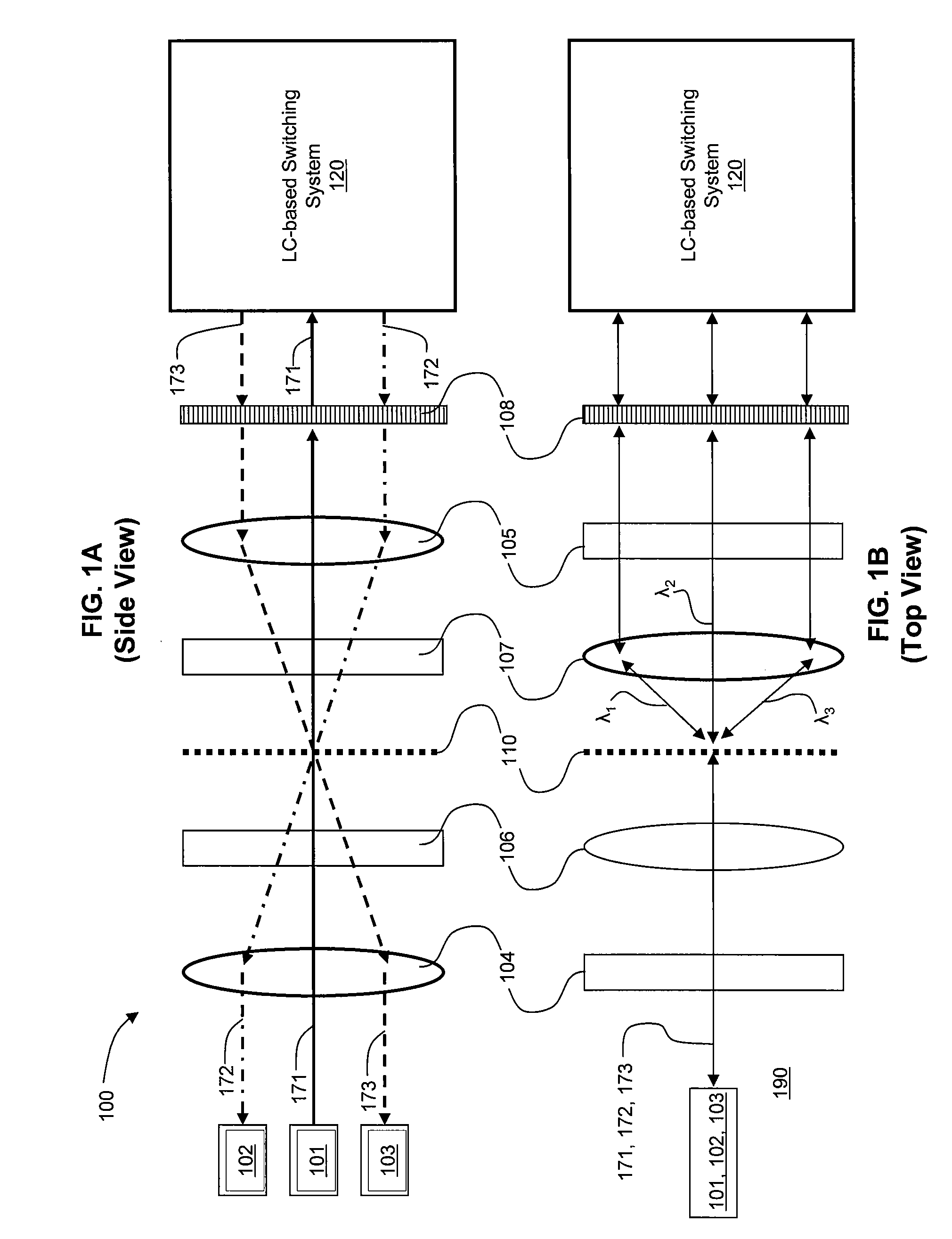
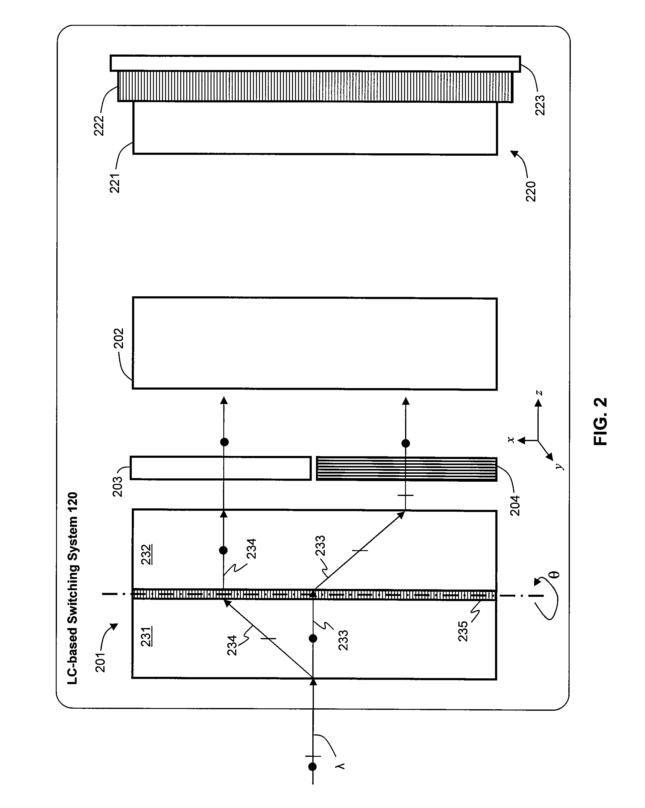
[0022]FIG. 1A is a schematic side view of a WSS 100 that performs 1×2 switching and attenuation of a WDM signal, according to an embodiment of the invention. FIG. 1B is a schematic top view of WSS 100. WSS 100 can selectively direct each of the wavelength channels of an input light beam to one of two output optical paths. For example, an input light beam containing a plurality of wavelength channels enters through an input fiber and each of the individual wavelength channels may be directed to o...


PUM

PropertyMeasurementUnit
angleaaaaaaaaaa
angleaaaaaaaaaa
angleaaaaaaaaaa

Abstract

An LC-based optical device compensates for differences in optical path lengths of polarization components of input beam. As a result, PDL and PMD of the optical device are reduced. The compensation mechanism may be a glass plate that is disposed in an optical path of a polarization component so that the optical path length of that polarization component can be made substantially equal to the optical path length of the other polarization component that traverses through a half-wave plate. Another compensation mechanism is a birefringent displacer that has two sections sandwiching a half-wave plate, wherein the two sections are of different widths and the planar front surface of the birefringent displacer can be positioned to be non-orthogonal with respect to the incident input light beam.

Description

BACKGROUND OF THE INVENTION[0001]1. Field of the Invention[0002]Embodiments of the present invention relate generally to optical communication systems and components and, more particularly, to a liquid crystal-based optical device that is configured to reduce polarization dependent loss and polarization mode dispersion.[0003]2. Description of the Related Art[0004]In optical communication systems, it is sometimes necessary to perform 1×2 switching of an optical signal, where an input light beam enters an optical switching device through an input port and is directed to one of two output ports. There are also more complicated optical switching schemes, such as 2×2, 1×N, and N×N optical switches, which may be realized by combining multiple 1×2 optical switches.[0005]In addition to routing of signals by optical switches, attenuation of signals in optical communication systems is needed, for example in an optical communication system that employs wavelength division multiplexing (WDM). I...

Claims


Application Information

Patent Timeline
Patent Type & Authority Applications(United States)
IPC IPC(8): G02F1/1335
CPCG02F1/13363G02F1/31G02F2201/17G02F2203/05
Inventor YUE, XUEFENGWANG, RUIBO
Owner II VI DELAWARE INC
Why Eureka
Try Eureka