All Reflective Apparatus for Injecting Excitation Light and Collecting In-elastically Scattered Light from a Sample

a reflective apparatus and inelastic optical spectroscopy technology, applied in the direction of optical radiation measurement, instruments, spectrometry/spectrophotometry/monochromators, etc., can solve the problems of inability to collect scattered radiation, loss of reflected scattered radiation of mirrors with holes, and inability to illuminate samples and collect scattered radiation. , to achieve the effect of maximizing field and maximizing rejection of unwanted radiation

Active Publication Date: 2010-12-02
DIABESEN TECH BEIJING CO LTD
View PDF7 Cites 7 Cited by
  • Summary
  • Abstract
  • Description
  • Claims
  • Application Information

AI Technical Summary

Benefits of technology

[0009]In one embodiment, in order to minimize the required wavelength guard-band between the excitation wavelength and the observed inelastic spectra, while simultaneously maximizing the field of view, the LWP filter is disposed at an angle with respect to the direction of propagation of the inelastic spectra that does not exceed a limit, which can be calculated from the ratio of the desired field of view to the focal length of the off-axis reflector. Based also on the compactness of the apparatus, this angle should have a lower bound and is advantageously chosen to be about 12°.
[0010]To maximize rejection of unwanted radiation at the excitation source wavelength, a second LWP filter disposed at an angle different from the first LWP filter can be deployed in the nominally collimated region.

Problems solved by technology

A mirror with a hole will exhibit losses with respect to the reflected scattered radiation, which may be important when the scattered signal is weak.
Another problem is that laser light may be scattered from the aperture in the mirror, or from optics on the side of the mirror opposite the excitation source, some of which scattered radiation may be incident on the spectroscopic apparatus.
The apparatus of Wheatley was intended for illumination only, and in particular, it is not suitable for both illumination of a sample and collection of the scattered radiation from the same side of the sample.
The apparatus of Wheatley would require optical access to a second side of the sample which is often impractical.

Method used


Image

  • All Reflective Apparatus for Injecting Excitation Light and Collecting In-elastically Scattered Light from a Sample
  • All Reflective Apparatus for Injecting Excitation Light and Collecting In-elastically Scattered Light from a Sample
  • All Reflective Apparatus for Injecting Excitation Light and Collecting In-elastically Scattered Light from a Sample

Examples


Embodiment Construction

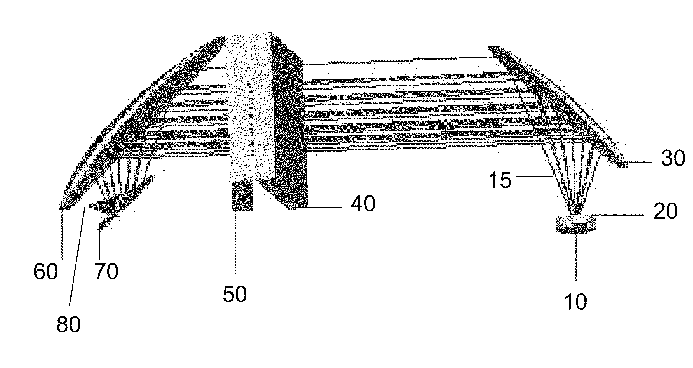
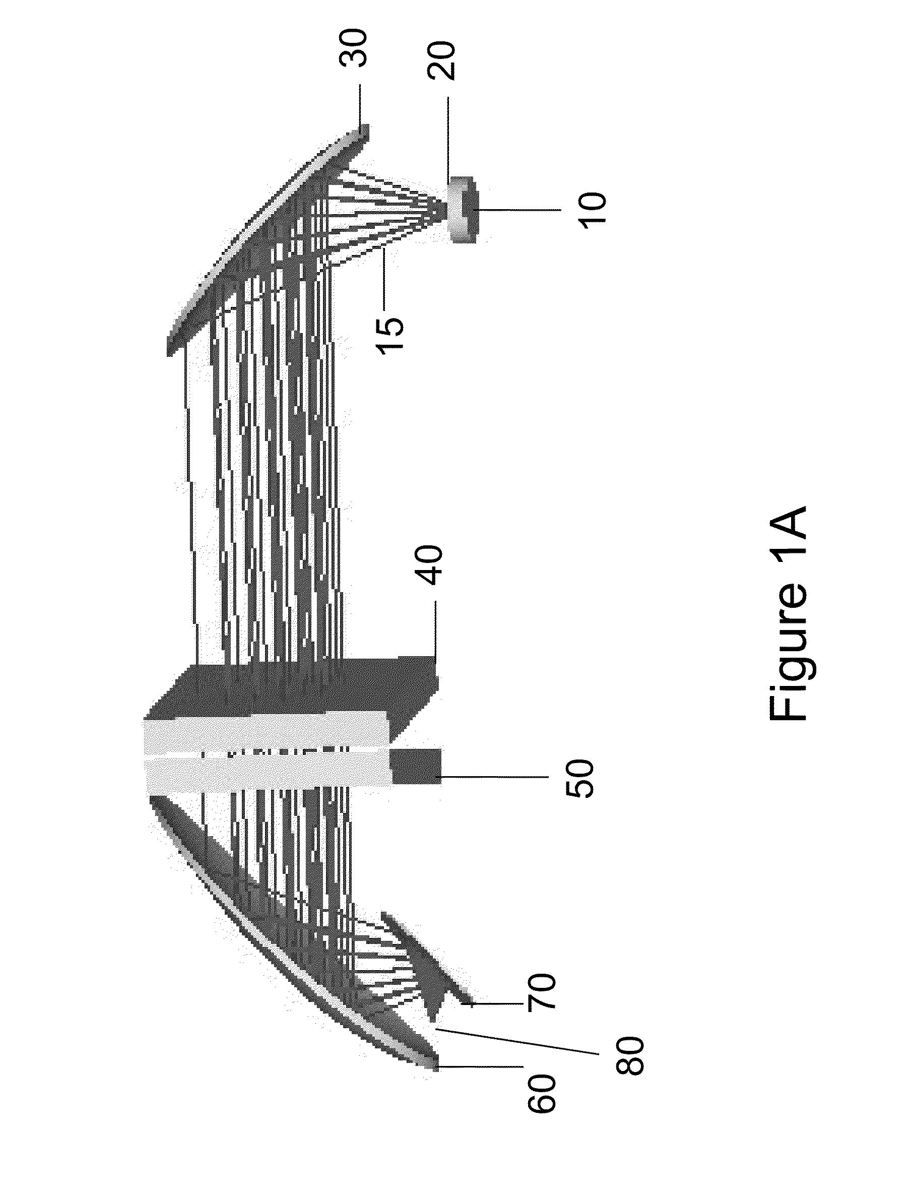
[0012]Referring to FIG. 1A, the radiation of the scattered inelastic spectrum 15 originates at point 10. After passing through an optical window 20, the radiation 15 is incident on off-axis reflector 30 which nominally collimates the light. The inelastic spectrum passes through a first LWP filter 40 and then through a second LWP filter 50. Note that the LWP filters 40, 50 are disposed at angles with respect to the direction of propagation of the nominally collimated inelastic spectra. The inelastic spectrum is then incident on the second off-axis reflector 60 reflected by plane mirror 70 and comes to focus in the neighborhood of point 80.

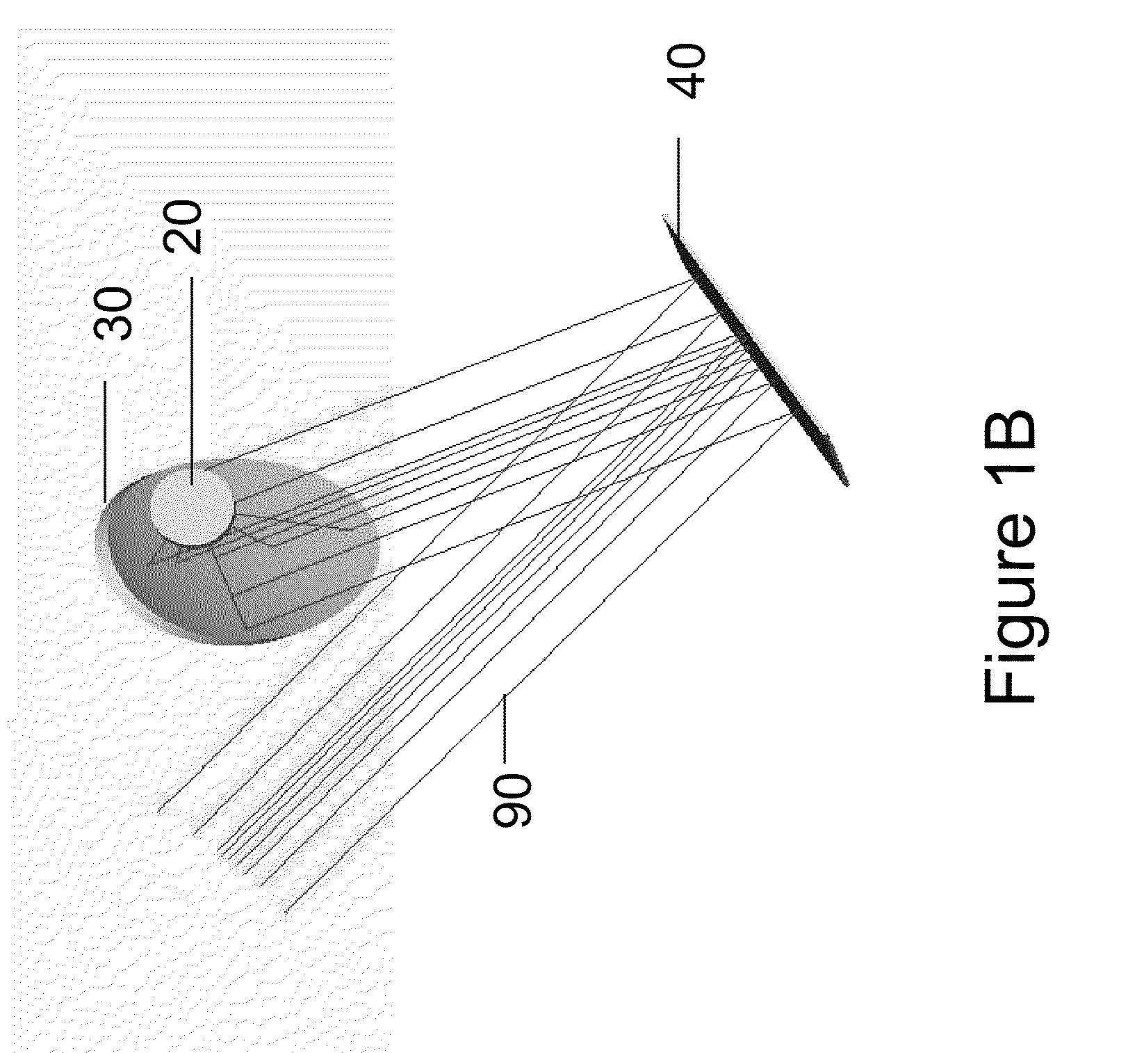
[0013]Referring to FIG. 1B, the excitation beam 90 is incident on LWP filter 40 by which it is reflected. The excitation beam 90 is then incident on off-axis reflector 30, and focused through window 20. The excitation beam 90 need not come to focus at point 10 of FIG. 1A and can in general be offset from the location from which the inelastic spectru...


PUM


Abstract

An apparatus is disclosed wherein laser radiation illuminates a sample using all reflective optics and wherein in-elastically scattered light from the sample is collected using the identical elements. The apparatus obviates the problem of contaminating the laser radiation with unwanted spectra from transmissive optics while providing very high rejection of the laser radiation with respect to the in-elastically scattered light. In addition, the apparatus can collect and launch light with high numerical aperture and large field of view.

Description

CROSS-REFERENCE TO RELATED APPLICATION[0001]This application claims priority under 35 U.S.C. §119(e) to U.S. Provisional Patent Application Ser. No. 61 / 183,470, filed Jun. 2, 2009, entitled “All Reflective Apparatus For Injecting Excitation Light And Collecting In-Elastically Scattered Light From A Sample,” which is incorporated herein by reference in its entirety.BACKGROUND OF THE INVENTION[0002]1. The Field of the Invention[0003]This invention relates in general to launching and collecting light for inelastic optical spectroscopy. Specifically, the invention shows how to preserve the spectral purity of the launched light with all reflective optics while simultaneously collecting light from a sample with a wide field of view, re-using the reflective optic nearest the sample and a filter which is used both to reflect the launched light and pass the in-elastically scattered light.[0004]2. Background and Relevant Art[0005]In performing inelastic optical spectroscopy, a sample is irrad...

Claims


Application Information

Patent Timeline
Patent Type & Authority Applications(United States)
IPC IPC(8): G01J3/44
CPCG01J3/02G01J3/0208G01J3/021G01J3/4412G01J2003/1226G01J2003/1247
Inventor LIPSON, JANICE, DONALD A.
Owner DIABESEN TECH BEIJING CO LTD
Why Eureka
Try Eureka