Two-shaft gas turbine

a gas turbine and two-shaft technology, applied in the field of gas turbines, can solve the problems of increasing the size of the gas turbine, and achieve the effects of reducing the pressure loss in the gas passage and the length of the gas passage, and improving performan

Inactive Publication Date: 2010-12-02
MITSUBISHI HEAVY IND LTD
View PDF8 Cites 29 Cited by
  • Summary
  • Abstract
  • Description
  • Claims
  • Application Information

AI Technical Summary

Benefits of technology

[0009]Accordingly, an object of the present invention is to provide a two-shaft gas turbine that is small and provides improved performance, wherein strut covers and first-stage stator blades are effectively integrated to reduce pressure loss in a gas passage and the length of the gas passage.

Problems solved by technology

Therefore, the length of the low-pressure turbine 102 along the rotor shaft is also increased, which leads to an increase in the size of the gas turbine.

Method used


Image

  • Two-shaft gas turbine
  • Two-shaft gas turbine
  • Two-shaft gas turbine

Examples


Embodiment Construction

[0024]A two-shaft gas turbine according to an embodiment of the present invention will be described in detail below with reference to the accompanying drawings.

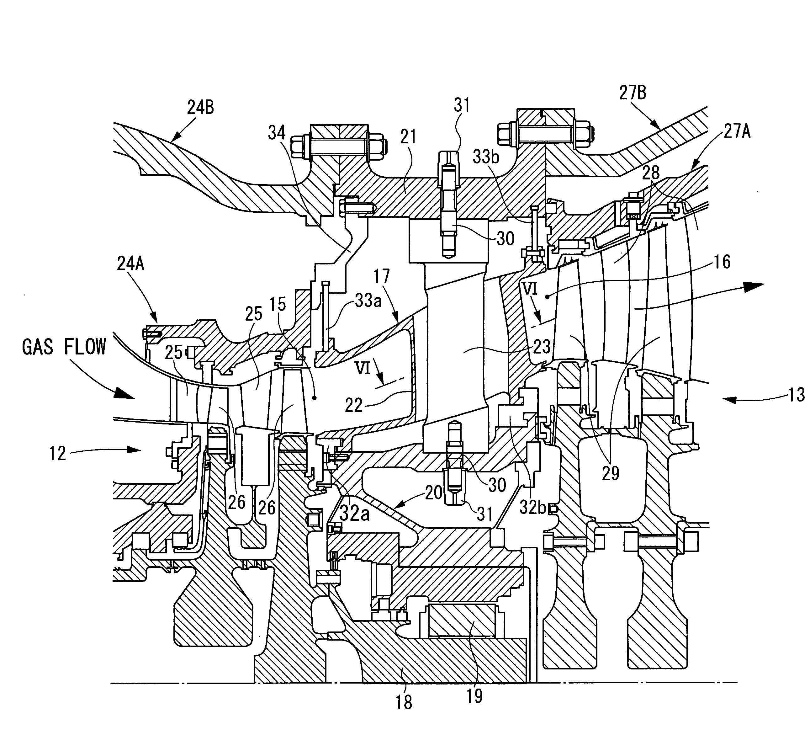
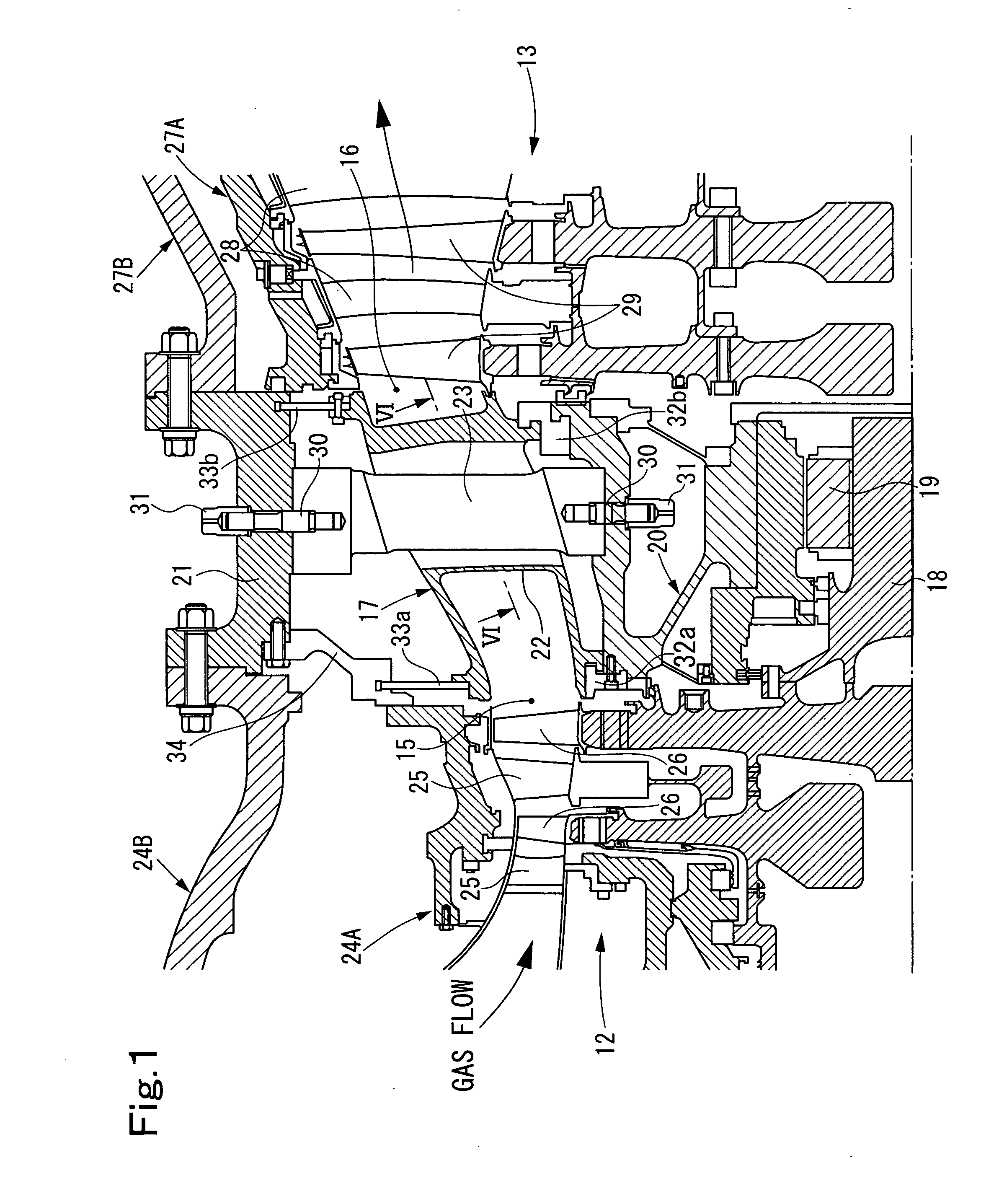
[0025]As shown in FIG. 5, a two-shaft gas turbine according to the present embodiment includes a compressor 10, a combustor 11, a high-pressure turbine 12 that functions as a gas generator, and a low-pressure turbine 13 that functions as a power turbine.

[0026]In this two-shaft gas turbine, air is compressed by the compressor 10 and is supplied to the combustor 11, where the compressed air is mixed with fuel that is separately supplied and the mixture of the compressed air and the fuel is combusted. Combustion gas is generated by combustion is supplied to the high-pressure turbine 12 and the low-pressure turbine 13. The high-pressure turbine 12 generates high-temperature, high-pressure combustion gas for driving the compressor 10 at, for example, 5,000 rpm and the low-pressure turbine 13 drives a generator 14 at, for example, ...


PUM


Abstract

A two-shaft gas turbine includes a high-pressure turbine having an annular gas-passage outlet, a low-pressure turbine having an annular gas-passage inlet, an annular intermediate duct that connects the gas-passage outlet to the gas-passage inlet, a bearing that supports a rotor of the high-pressure turbine and that is attached to a bearing case, and a plurality of struts that support the bearing case. The struts are arranged radially along the circumference of the bearing case so as to extend though the intermediate duct in a space between an outer peripheral surface of the bearing case and an inner peripheral surface of a casing wall that surrounds the intermediate duct. The intermediate duct has strut covers through which the struts extend and which function as first-stage stator blades for the low-pressure turbine.

Description

BACKGROUND OF THE INVENTION[0001]1. Field of the Invention[0002]The present invention relates to a gas turbine including a plurality of shafts arranged on the same axis.[0003]2. Description of the Related Art[0004]A typical gas turbine (not shown) includes a compressor, a combustor, and a turbine. In the gas turbine, air is compressed by the compressor and is supplied to the combustor, where the compressed air is mixed with fuel that is separately supplied and the mixture of the compressed air and the fuel is combusted. Combustion gas is generated by combustion and is supplied to the turbine, where energy of the combustion gas is extracted. The energy exerts a rotational driving force for the compressor and a driving force for causing a generator (not shown) to generate electricity. After the rotational driving force is generated by the turbine, the combustion gas is exhausted through an exhaust diffuser.[0005]FIG. 7 shows an example of a commonly known two-shaft gas turbine used as...

Claims


Application Information

Patent Timeline
Patent Type & Authority Applications(United States)
IPC IPC(8): F01D1/24
CPCF01D25/162
Inventor KATAOKA, MASAHITOITO, EISAKULAURELLO, VINCENT
Owner MITSUBISHI HEAVY IND LTD
Why Eureka
Try Eureka