Recovery tip turbine blade

Active Publication Date: 2010-12-02
GENERAL ELECTRIC CO
View PDF39 Cites 71 Cited by
  • Summary
  • Abstract
  • Description
  • Claims
  • Application Information

AI Technical Summary

Benefits of technology

[0021]Various blade permutations may now be more readily analyzed to pred

Problems solved by technology

However, aerodynamic design of turbine airfoils is remarkably complex in view of the three dimensional (3D) configurations of the individual airfoils in complete rows thereof, and the correspondingly complex flow streams of the combustion gases channeled between the airfoils during operation.
However, the combustion gases which leak over the airfoil tips in the required tip clearance perform little, if any, useful work.
The tip ribs increase the complexity of the combustion gas flow field introducing local secondary fields which affect turbine efficiency, flow leakage, and tip cooling.
These three important considerations are interdependent at least in part, but the complex 3D flow fields over the different pressure and suction sides at the airfoil tip and between the leading and trailing edges renders quite complex the evaluation thereof.
Furthermore, it is common practice to continually improve existing blade designs, but any change in blade design, and particularly in the tip, is interdependent with other blade features and might adversely affect the blade.
Typical blade design requires careful balance of competing objectives and the careful evaluation of particular operating conditions, and this further complicates modern blade design.
Features which provide benefit in one blade design do not necessarily provide benefit in other designs for which they were not originally designed.
Predictability of performance of individual features is illusory when introduced in different blades designed for different operating conditions.

Method used


Image

  • Recovery tip turbine blade
  • Recovery tip turbine blade
  • Recovery tip turbine blade

Examples


Embodiment Construction

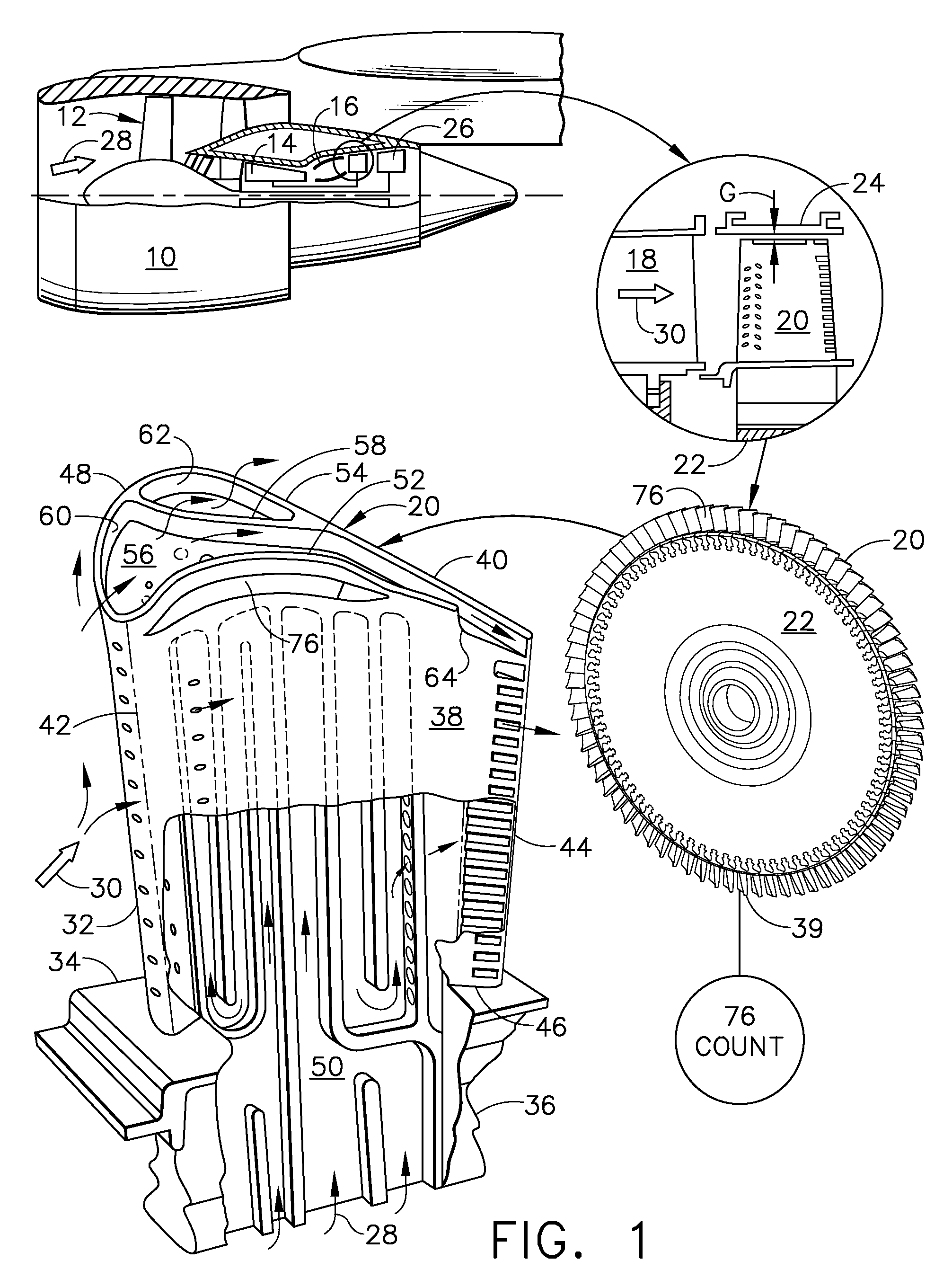
[0030]Illustrated schematically in FIG. 1 is an exemplary turbofan gas turbine engine 10 mounted to an aircraft wing (shown in part) for powering an aircraft in flight.

[0031]The engine 10 is axisymmetrical about a longitudinal or axial centerline axis, and includes in serial flow communication a fan 12, compressor 14, and combustor 16 followed by a single-stage HPT. The HPT includes a nozzle 18 and a row of first stage turbine rotor blades 20 extending radially outwardly from a supporting rotor disk 22.

[0032]The row of blades 20 is mounted inside a surrounding turbine shroud 24 with a small radial clearance or tip gap G therebetween. And, a multistage LPT 26 follows the single stage HPT.

[0033]During operation, air 28 enters the engine and is pressurized in the compressor and mixed with fuel in the combustor. Hot combustion gases 30 then leave the combustor to power the HPT and LPT which in turn power the compressor and fan.

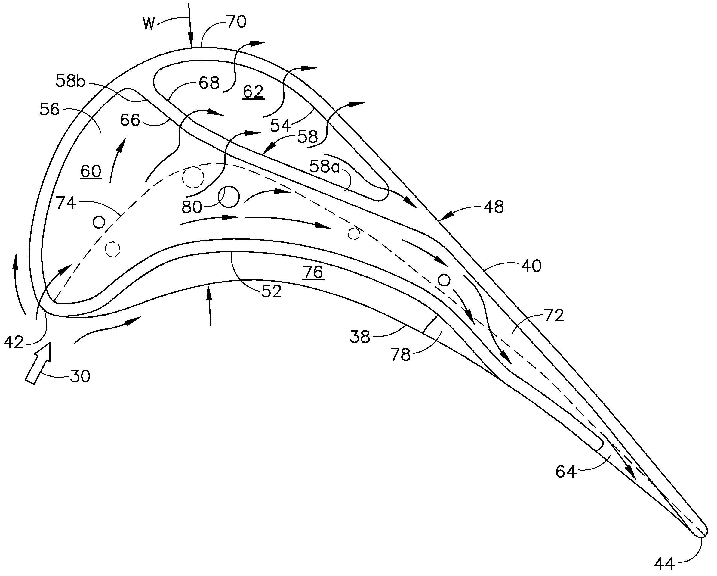
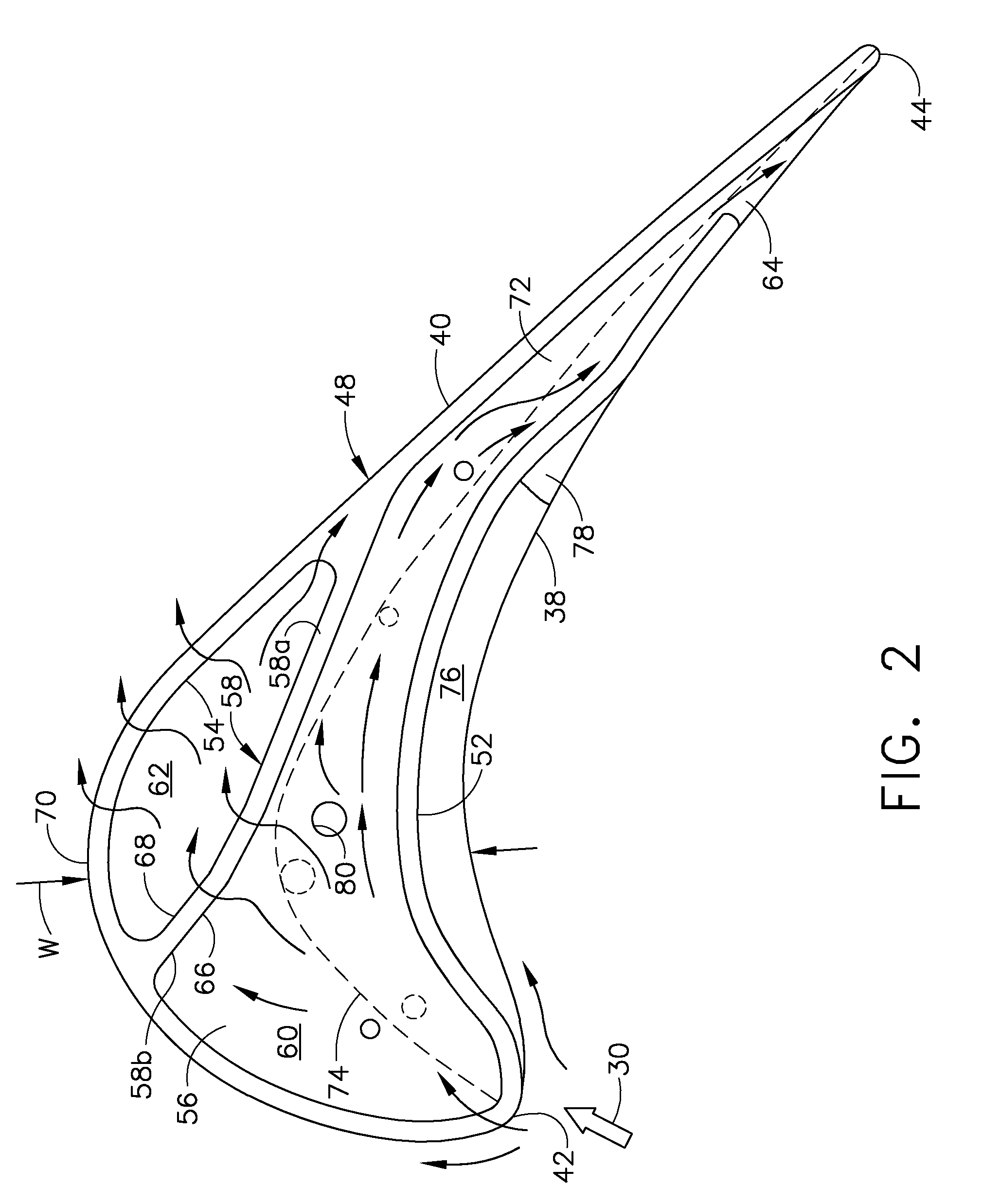
[0034]The exemplary turbine blade 20 is typically cast from ...


PUM

PropertyMeasurementUnit
Pressureaaaaaaaaaa
Widthaaaaaaaaaa
Heightaaaaaaaaaa

Abstract

A turbine blade includes an airfoil having first and second tip ribs extending along the opposite pressure and suction sides thereof. A tip baffle bifurcates the airfoil tip into two pockets, with a first pocket being laterally open at its aft end to recover leakage flow, and a second pocket being laterally closed.

Description

BACKGROUND OF THE INVENTION[0001]The present invention relates generally to gas turbine engines, and, more specifically, to turbine blades therein.[0002]In a gas turbine engine, air is pressurized in a compressor and mixed with fuel for generating combustion gases in a combustor. Various turbine stages extract energy from the combustion gases to power the engine and produce work.[0003]A high pressure turbine (HPT) immediately follows the combustor and extracts energy from the hottest combustion gases to power the upstream compressor through one drive shaft. A low pressure turbine (LPT) follows the HPT and extracts additional energy from the combustion gases for powering another drive shaft. The LPT powers an upstream fan in a turbofan aircraft engine application, or powers an external shaft for marine and industrial applications.[0004]Engine efficiency and specific fuel consumption (SFC) are paramount design objectives in modern gas turbine engines. The various turbine rotor blades ...

Claims


Application Information

Patent Timeline
IPC IPC(8): F01D5/18B22D19/00
CPCF01D5/20Y02T50/673Y02T50/60
Inventor KUHNE, CRAIG MILLERBUBNICK, JOSEPH STEVENVACHHANI, ALISHA
Owner GENERAL ELECTRIC CO
Why Eureka
Try Eureka