Capillary pump unit and flow cell

a capillary pump and flow cell technology, which is applied in the direction of positive displacement liquid engines, instruments, laboratory glassware, etc., can solve the problems of limited use to a small amount of sample liquid, the capacity of the capillary pump is necessarily limited to the height range of the flow channel, and the difficulty of fabricating such a device, etc., to achieve the effect of high pump capacity, small size and sufficient pump capacity

Active Publication Date: 2010-12-02
NIPPON TELEGRAPH & TELEPHONE CORP
View PDF9 Cites 10 Cited by
  • Summary
  • Abstract
  • Description
  • Claims
  • Application Information

AI Technical Summary

Benefits of technology

[0056]With the capillary pump unit according to the present invention, sufficient pump capacity can be reserved without increasing the area in a plane direction, thus obtaining high pump capacity and achieving a small size and low cost. In addition, a structure having a high aspect ratio can be readily made by stacking the sheet-shaped bases, thus obtaining high pump capacity. Also, the through portions of the respective sheet-shaped bases are communicable with one another, thus realizing a highly efficient use of space.
[0057]Furthermore, with the flow cell according to the present invention, a sample liquid can be continuously flowed by employing the capillary pump unit, such that measurement by the detector can be successfully performed and high reliability of the measurement result can be obtained.

Problems solved by technology

Accordingly, it is difficult to fabricate such a device.
As a result, a transfer path, such as a tube, makes dead volume of the sample liquid, which limits use to a small amount of the sample liquid.
However, in techniques of Patent Document 5 and Non-Patent Document 2, since a flow channel formed on a substrate has an additional function to serve as a capillary pump, the capacity of the capillary pump is necessarily limited to a height range of the flow channel.
Accordingly, in order to sufficiently reserve the capacity of the pump, it is necessary to extend the measuring chip in a plane direction, which makes it difficult to fabricate the measuring chip with a small size and at a low cost.
Meanwhile, since lithography or etching is performed on a substrate formed of a material or a substrate itself having a groove as a flow channel is fabricated by injection molding to fabricate the measuring chip, it is difficult to fabricate a structure of a high aspect ratio.
Accordingly, since the capacity of the pump is limited, the amount of the sample liquid flowing through the measurement flow channel is also limited and the sample liquid cannot be continuously flowed for sufficient measurement.
Also, in the fabricating method, because it is difficult to process the inside of the substrate, locations in the substrate at which a flow channel or a pump can be fabricated are limited, making it impossible to fabricate a structure with a high efficient use of space.

Method used


Image

  • Capillary pump unit and flow cell
  • Capillary pump unit and flow cell
  • Capillary pump unit and flow cell

Examples


first embodiment

[0082]Hereinafter, the present invention will be described with reference to the accompanying drawings.

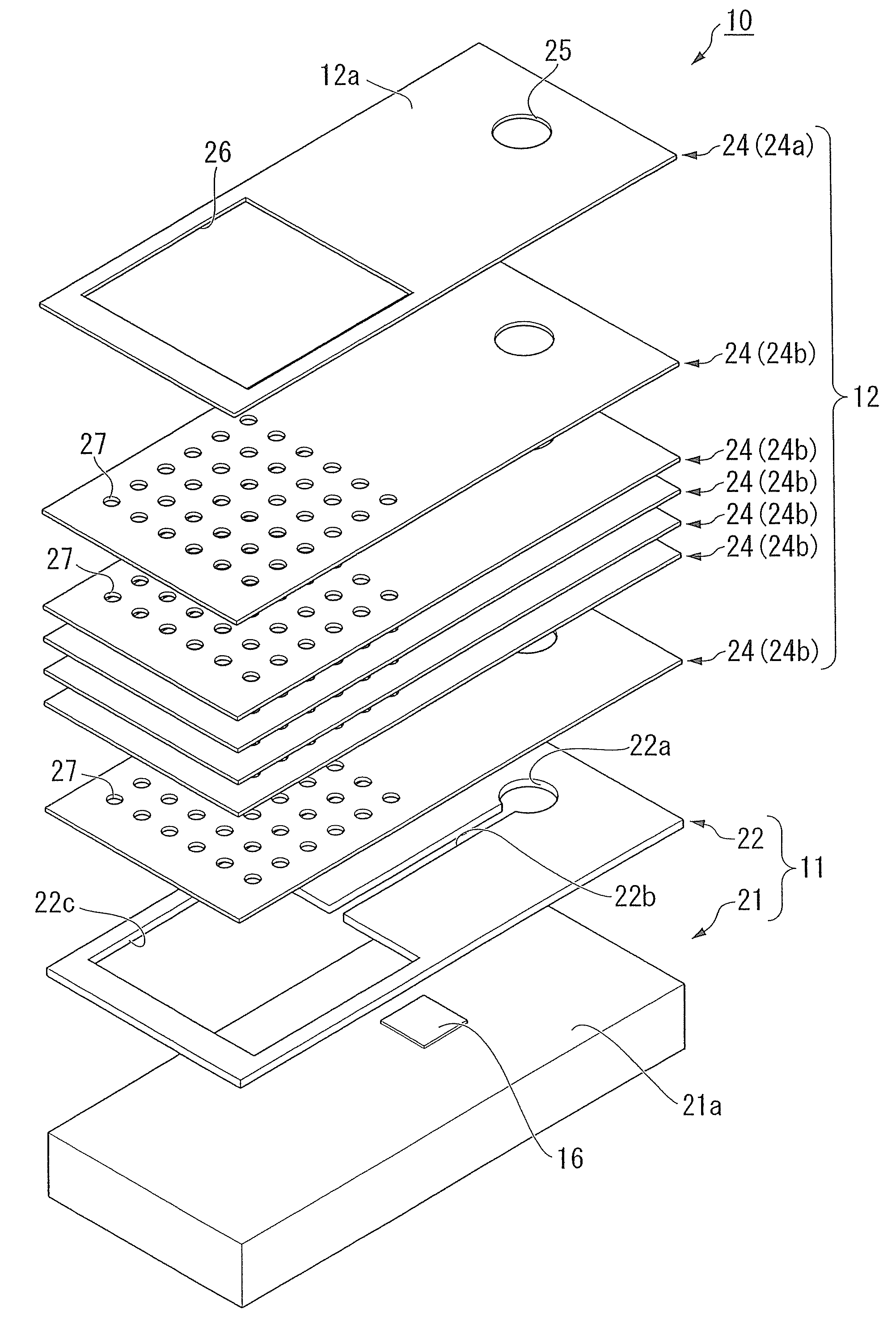
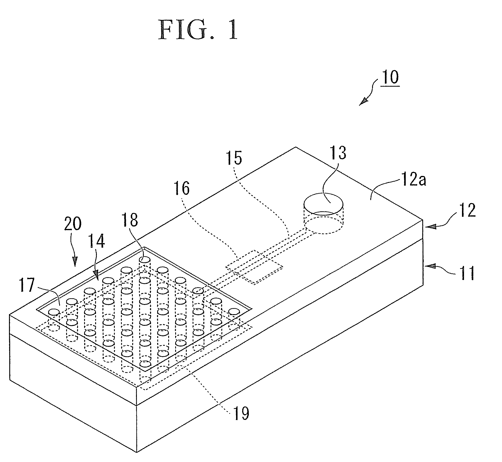
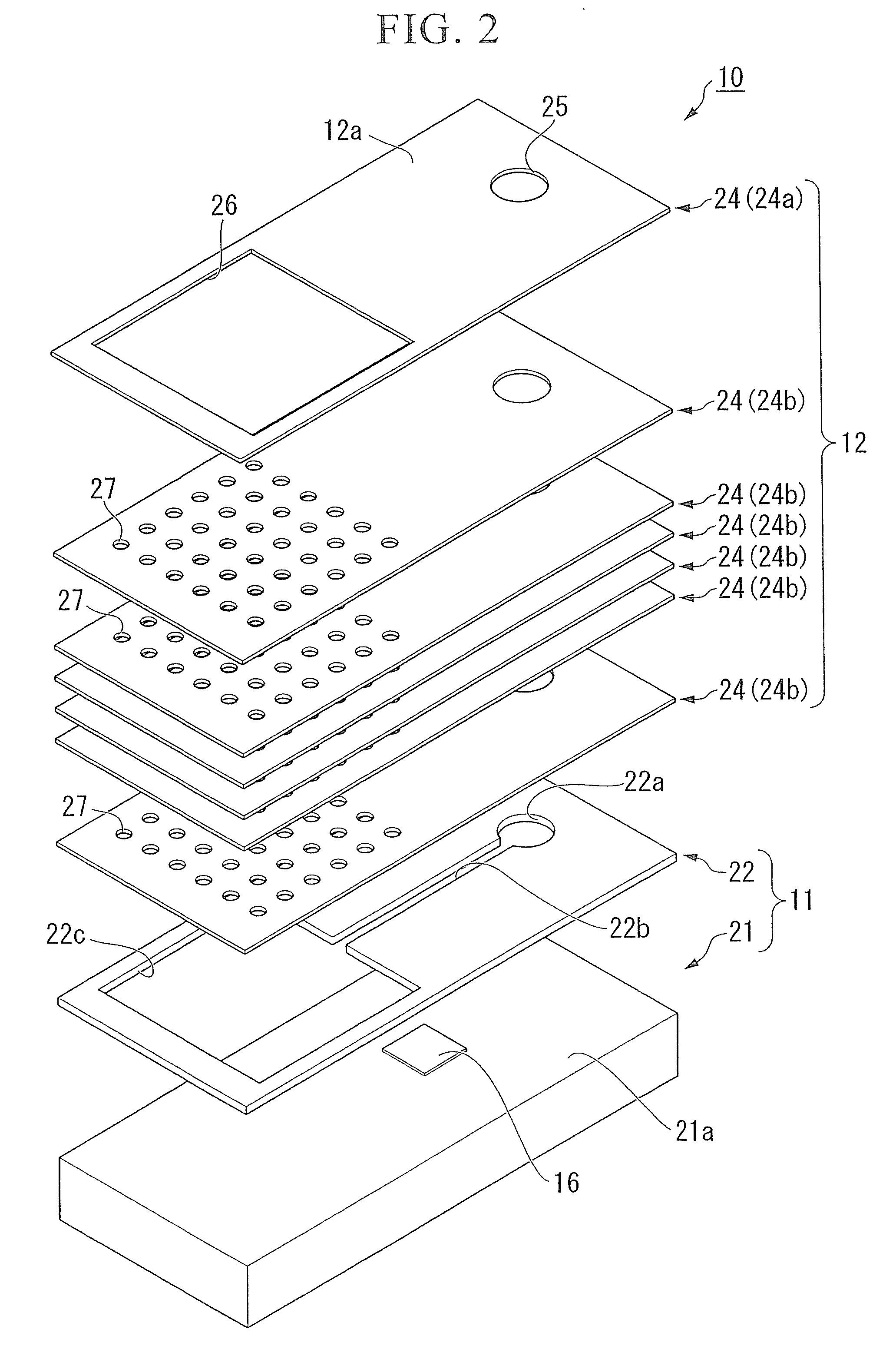
[0083]FIG. 1 is a perspective view of a flow cell according to the first embodiment, and FIG. 2 is an exploded perspective view of the flow cell according to the first embodiment.

[0084]As shown in FIG. 1, a flow cell 10 of the present embodiment is formed by stacking a flat-plate-shaped capillary pump unit 12 disposed with the same outside dimension as an approximately flat-plate-shaped substrate 11 that is in a rectangular shape when viewed from above, on the substrate 11.

[0085]An inlet 13 through which a sample liquid (referred to as a sample) is introduced, a capillary pump 14 which suctions the sample liquid up, a suction flow channel 19 disposed beneath the capillary pump 14, a measurement flow channel 15 that connects between the suction flow channel 19 and the inlet 13, a detector 16 provided on the measurement flow channel 15, and an outlet portion 17 disposed on the capill...

second embodiment

[0131]Next, the present invention will be described with reference to the accompanying drawings.

[0132]FIG. 8 is a perspective view of a flow cell according to the second embodiment, FIG. 9 is an exploded perspective view of the flow cell according to the second embodiment, and FIG. 10 is a plan view of the flow cell according to the second embodiment. Also, in FIGS. 8 and 9, like numbers are used to refer to the same components as those of the flow cell 10 of the first embodiment and a detailed description thereof will be omitted.

[0133]A flow cell 30 of the present embodiment differs from the flow cell 10 of the first embodiment in formation regions of the suction flow channel 19 and the cylindrical holes 18.

[0134]That is, as shown in FIG. 9, the same flow channel groove 22b as in the first embodiment is formed in a spacer portion 22 of a substrate 11 in the present embodiment and a meandering groove 31 extending from a second end of the flow channel groove 22b is formed. The meande...

third embodiment

[0156]Also, in the flow cell 40 of the third embodiment, for example, a surface active region 45 having a different wettability for a sample liquid than other regions may be formed on a surface of the base substrate 21 in a formation region for the suction flow channel 44, as shown in FIG. 13. Since an expanding state of the sample liquid in the surface active region 45 differs from that of other regions, a suction state of the sample liquid in the suction flow channel 44 can controlled and the flow rate of the sample liquid flowing the measurement flow channel 15 can be changed by changing an area of the surface active region 45. Also, the formation region for the surface active region 45 is not limited to the formation region for the suction flow channel 44, but may be provided in the formation region for the measurement flow channel 15.

[0157]The surface active region 45 can be formed by performing surface processing, for example, with BlockAce (registered trademark of Dainippon S...


PUM

PropertyMeasurementUnit
heightaaaaaaaaaa
heightaaaaaaaaaa
thicknessaaaaaaaaaa

Abstract

In a capillary pump unit, a capillary pump including a plurality of through portions making a first point and a second point of an approximately flat-plate-shaped base communicable with each other are formed in the base, and a sample liquid is transferred from the first point to the second point by capillary force by the through portions.

Description

TECHNICAL FIELD[0001]The present invention relates to a capillary pump unit which suctions a sample liquid as a target using a capillary force, and a flow cell including the capillary pump unit.[0002]The present application claims priority on Japanese Patent Applications No. 2008-001064 filed on Jan. 8, 2008 and No. 2008-246604 filed on Sep. 25, 2008, the entire contents of which are incorporated herein by reference.BACKGROUND ART[0003]Measurement using an enhanced biomolecular identification function such as coupling of antigen-antibody reaction or DNA fragment (DNA probe) and DNA is an important technique for measurement in the field of laboratory testing and biochemistry and measurement of environmental pollution substances.[0004]Examples include micro total analysis systems (TASs), micro combinatorial chemistry, chemical IC, chemical sensors, bio sensors, micro analysis, electrochemistry analysis, QCM measurement, SPR measurement, ATR measurement, and so on, but in such measurem...

Claims


Application Information

Patent Timeline
Patent Type & Authority Applications(United States)
IPC IPC(8): G01N33/48F15C1/06B01J19/00G01N21/05G01N37/00
CPCB01L3/50273B01L3/502746B01L2200/027B01L2300/0816B01L2300/0887B01L2400/0406F04B19/006G01N21/05G01N21/553G01N2021/0346G01N2021/056G01N2021/058G01N2035/00237G01N2035/1037Y10T137/2224
Inventor HORIUCHI, TSUTOMUMIURA, TORUIWASAKI, YUZURUSEYAMA, MICHIKOHAYASHI, TSUYOSHITAKAHASHI, JUN-ICHIHAGA, TSUNEYUKI
Owner NIPPON TELEGRAPH & TELEPHONE CORP
Why Eureka
Try Eureka