Non-kinematic behavioral mapping

a non-kinematic behavioral and mapping technology, applied in the field of pedestrian warning systems, can solve the problems of reducing the response time of the driver of the vehicle, increasing the amount of time required by the vehicle-mounted system to process information, and delay between receip

Active Publication Date: 2010-12-02
RAYTHEON CO
View PDF16 Cites 71 Cited by
  • Summary
  • Abstract
  • Description
  • Claims
  • Application Information

AI Technical Summary

Benefits of technology

[0023]In view of the above, it has been recognized that there exists a need for an obstacle detection mapping system which can compactly represent the predicted future locati

Problems solved by technology

The increase in the amount of transmitted information results in a concomitant increase in the amount of time required by vehicle-mounted systems to process the information.
This results in a delay between the receipt of the object location information and a collision warning.
This delay reduces valuable response time for a driver of the vehicle and thus makes it more difficult for a driver to take evasive acti

Method used


Image

  • Non-kinematic behavioral mapping
  • Non-kinematic behavioral mapping
  • Non-kinematic behavioral mapping

Examples


Embodiment Construction

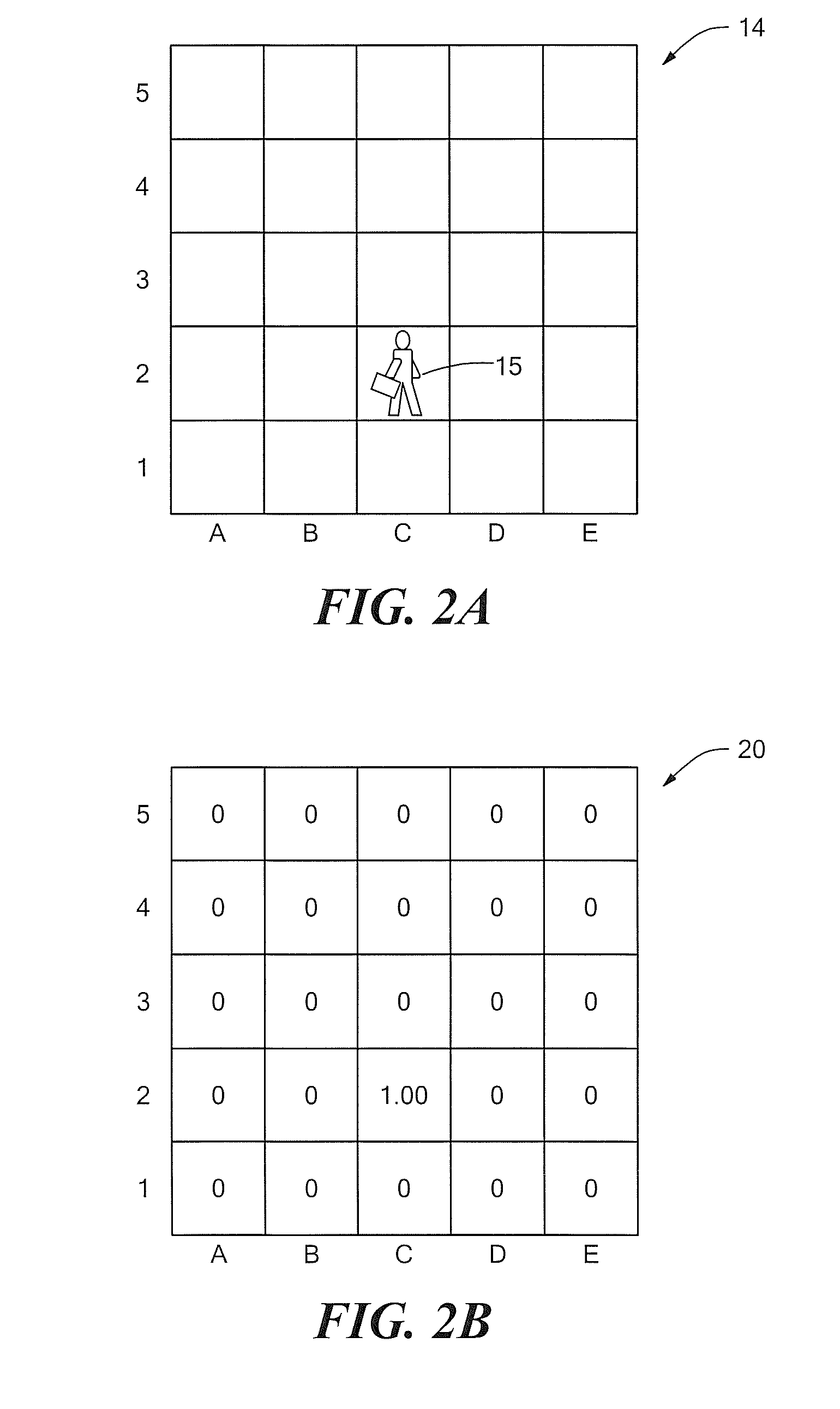
[0040]Described herein is a system and methodology / processes for non-kinematic / behavioral mapping to a local area abstraction (LAA) including a methodology for populating an LAA wherein human behavior or behavior of other objects having other non-strictly-kinematic motion may be present. Before describing such a system and related processes, some introductory concepts and terminology are explained.

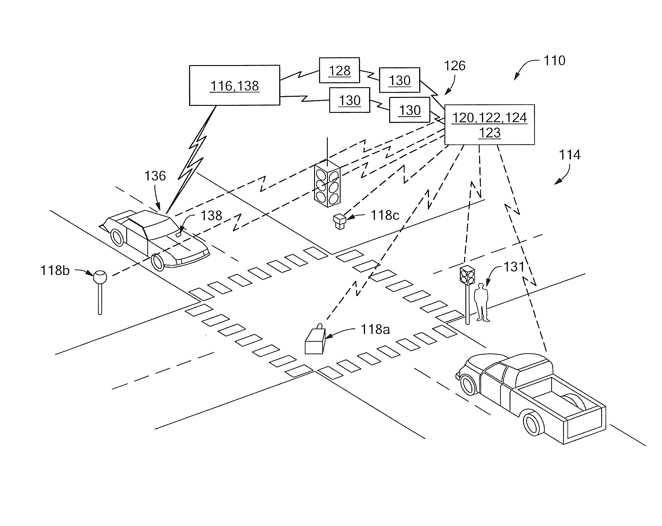
[0041]Reference is sometimes made herein to the use of systems and techniques in vehicular safety applications. One such vehicular safety application is referred to as a pedestrian warning system (PWS) which includes a pedestrian prediction logic (PPL) system which is an embodiment of a non-kinematic behavioral mapping system and related techniques used to predict pedestrian locations.

[0042]It should, of course, be appreciated that a PWS is but one specific example of a more general object warning system (OWS) and that the general concepts and techniques described herein are not limited to...


PUM


Abstract

A system and methodology/processes for non-kinematic/behavioral mapping to a local area abstraction (LAA) includes a technique for populating an LAA wherein human behavior or other non-strictly-kinematic motion may be present.

Description

CROSS REFERENCE TO RELATED APPLICATIONS[0001]This application claims priority under 35 U.S.C. §119(e) from U.S. Provisional Patent Application No. 61 / 182,877 filed Jun. 1, 2009 which application is hereby incorporated herein by reference in its entirety for all purposes.FIELD OF THE INVENTION[0002]The concepts, systems and techniques described herein relate generally to pedestrian warning systems and more particularly to a method and apparatus for mapping current and future predicted object locations to a local area abstraction (LAA).BACKGROUND OF THE INVENTION[0003]As is known in the art, object detection systems for vehicle collision systems are known and used to convey the location of objects that could potentially collide with a vehicle. One previously known way to describe the location of an obstacle is to describe the latitude and longitude of the object. As the number of objects increases, however, the amount of information that must be transmitted to the vehicle also increas...

Claims


Application Information

Patent Timeline
IPC IPC(8): G08G1/16G06N7/02
CPCG06K9/00785G06N7/02G08G1/166G06V20/54
Inventor RICHARDSON, JAMES J.
Owner RAYTHEON CO
Why Eureka
Try Eureka