Burner injection system for glass melting

a technology of glass melting and injection system, which is applied in the direction of glass tempering apparatus, combustion type, lighting and heating apparatus, etc., can solve the problems of burner maintenance and repair, operation, monitoring, and localized wear, and achieve the effect of reducing the number of burners

Inactive Publication Date: 2010-12-09
LINDE AG
View PDF20 Cites 64 Cited by
  • Summary
  • Abstract
  • Description
  • Claims
  • Application Information

AI Technical Summary

Problems solved by technology

In such systems combustion space and exhaust gas temperatures can be high and result in high NOx emissions and heat losses in the exhaust gas.
However, submerged combustion burners a

Method used


Image

  • Burner injection system for glass melting
  • Burner injection system for glass melting
  • Burner injection system for glass melting

Examples


Embodiment Construction

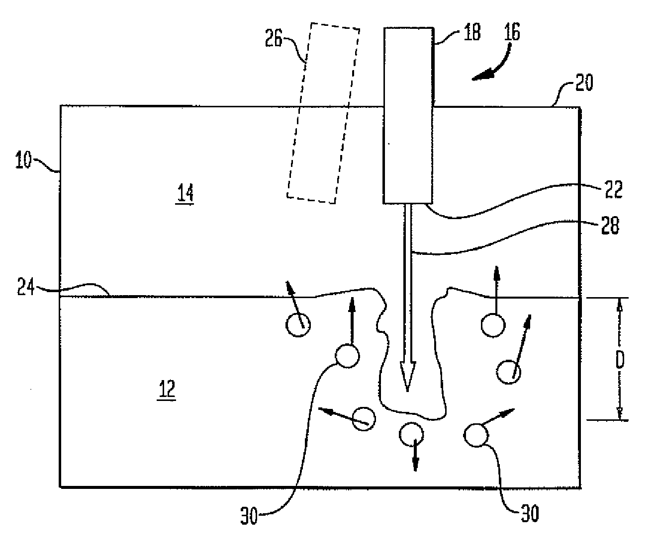
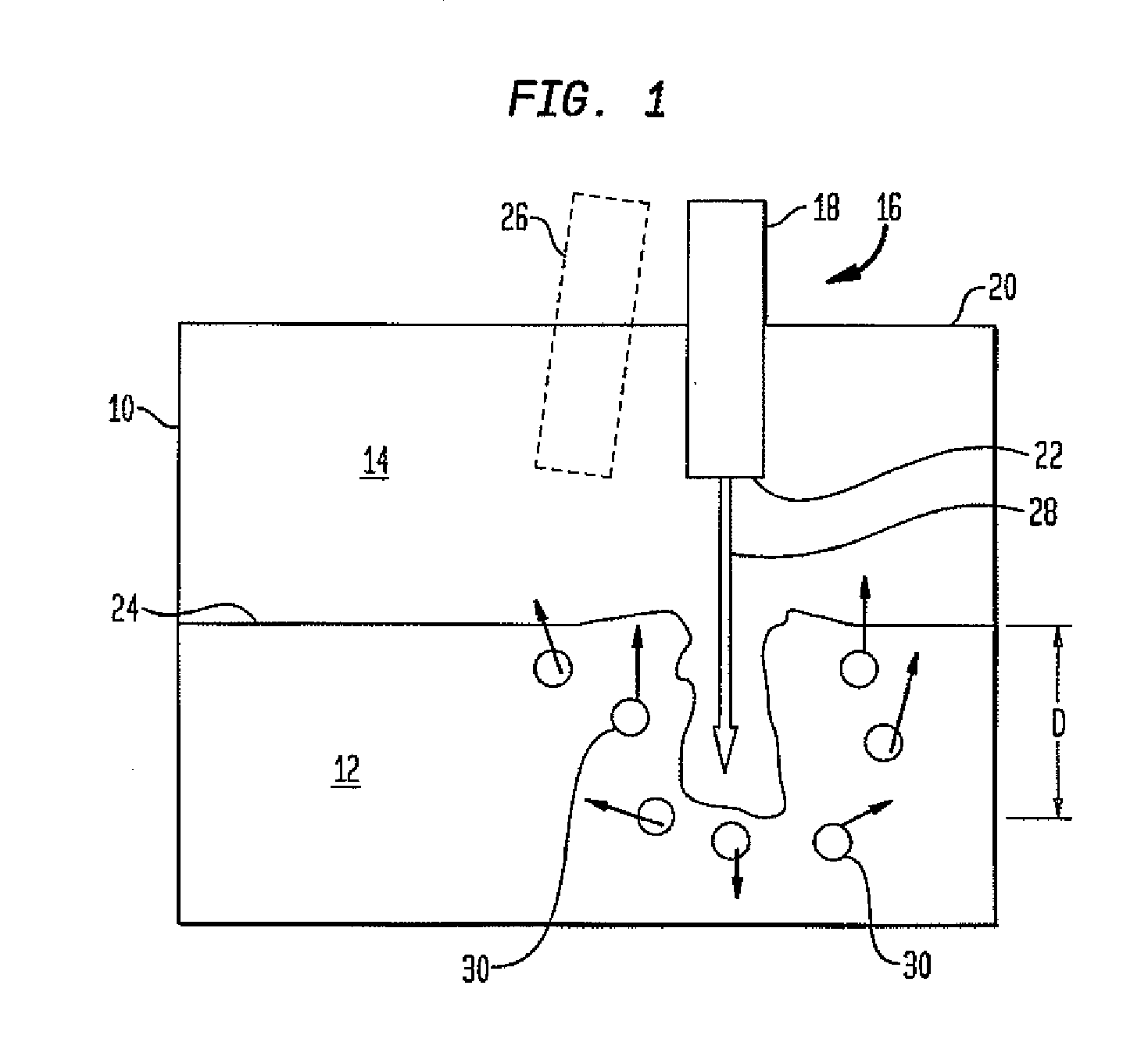
[0010]By impinging the surface of the glass with a supersonic combusting jet such that the combusting jet displaces a surface of the glass melt and penetrates into the melt, the benefits of submerged combustion (better heat transfer, high efficiency, low NOx, better mixing, rapid melting) are achieved without the need for a burner or injector to be placed below the glass level.

[0011]A further embodiment is the inclusion (by injection or otherwise) of glass forming batch material in the supersonic combusting jet or flame in such a manner that the solid material is directly injected into the body of the glass melt rather than floating on the surface. This further enhances the penetration of the supersonic combusting jet into the melt, and the mixing of the batch and glass material.

[0012]The process of creating a submerged combustion effect by impingement of a high momentum supersonic combusting jet from above and its penetration into a bath of liquid glass may include the burner and f...


PUM

PropertyMeasurementUnit
Forceaaaaaaaaaa
Angleaaaaaaaaaa

Abstract

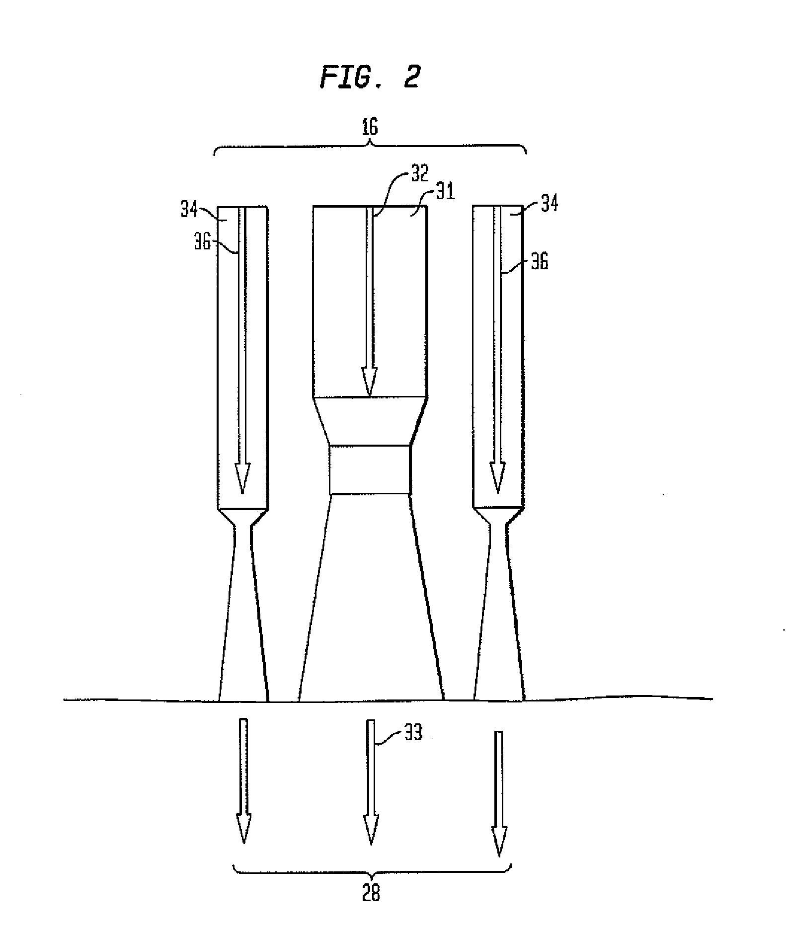
A burner for melting glass forming batch material includes a burner assembly constructed and arranged with a first passage for providing a fuel stream and a second passage for providing an oxidant stream, the first and second streams coacting to produce a supersonic combustion jet flame penetrable into glass melt. A method for melting glass forming batch material is also provided and includes providing a fuel stream; providing an oxidant stream; mixing the fuel and oxidant streams with sufficient force for providing a supersonic combustion jet flame; directing the supersonic combustion jet flame to contact the glass forming batch material; and penetrating the glass forming batch material to a select depth with the supersonic combustion jet flame.

Description

BACKGROUND OF THE INVENTION[0001]The inventive embodiments relate to melting glass batch materials.[0002]The melting of glass by combustion processes, in particular high efficiency melting, may include submerged combustion, wherein the flame is injected via burners mounted below the glass melt level. A similar effect may be created by impinging a high velocity flame downward onto and penetrating into the liquid bath, as practiced in an electric arc furnace (EAF) for the steel industry.[0003]Conventional glass melting from above depends upon the transfer of heat from above the glass surface and by heat transferred by the liquid glass flowing under the unmolten batch material. The rate at which this heat is transferred from above the glass is dependent largely upon radiation from the crown material which imposes an upper limit on the amount of heat transferred and thus the production rate of the furnace. Heat transfer to the upper surface of the glass melt may be augmented by the natu...

Claims


Application Information

Patent Timeline
IPC IPC(8): C03B5/16C03B19/00
CPCC03B3/026C03B5/235C03B5/2356C03B5/202F23D14/32Y02E20/344F23D14/22
Inventor RICHARDSON, ANDREW P.
Owner LINDE AG
Why Eureka
Try Eureka