Operating device with gate shafts

a technology of operating device and gate shaft, which is applied in the direction of mechanical control devices, manual control with single controlling member, instruments, etc., can solve the problems of structural complexity, corresponding cost, and the inability of the driver to obtain visual or haptic feedback about the gear state of the transmission, so as to achieve robust and space-saving design

Inactive Publication Date: 2010-12-09
ZF FRIEDRICHSHAFEN AG
View PDF23 Cites 30 Cited by
  • Summary
  • Abstract
  • Description
  • Claims
  • Application Information

AI Technical Summary

Benefits of technology

[0033]This results in a robust and space-saving design of the support and the entire shift kinematics of the selector lever using only one bearing shaft. As a result, the actuating device can be made compact, particularly in the vertical direction. Nevertheless, the distances between the individual shift positions of the selector lever are required not to be too small

Problems solved by technology

However, when gears are shifted electrically, which is becoming increasingly more common, that is, when gear shifting transmissions are actuated using shift-by-wire controls, the selector lever in the passenger compartment and the motor vehicle transmission in the engine compartment are usually not mechanically coupled.
In shift-by-wire gear shifting transmissions, however, the absence of a mechanical connection between the transmission actuator system and the selector lever can, under certain basic conditions, lead to the selector lever position no longer coinciding with the gear state of the transmission.
When a monostable selector lever is utilized, however, the driver is unable to obtain visual or haptic feedback about the gear state of the transmission based on the posit

Method used


Image

  • Operating device with gate shafts
  • Operating device with gate shafts
  • Operating device with gate shafts

Examples


Embodiment Construction

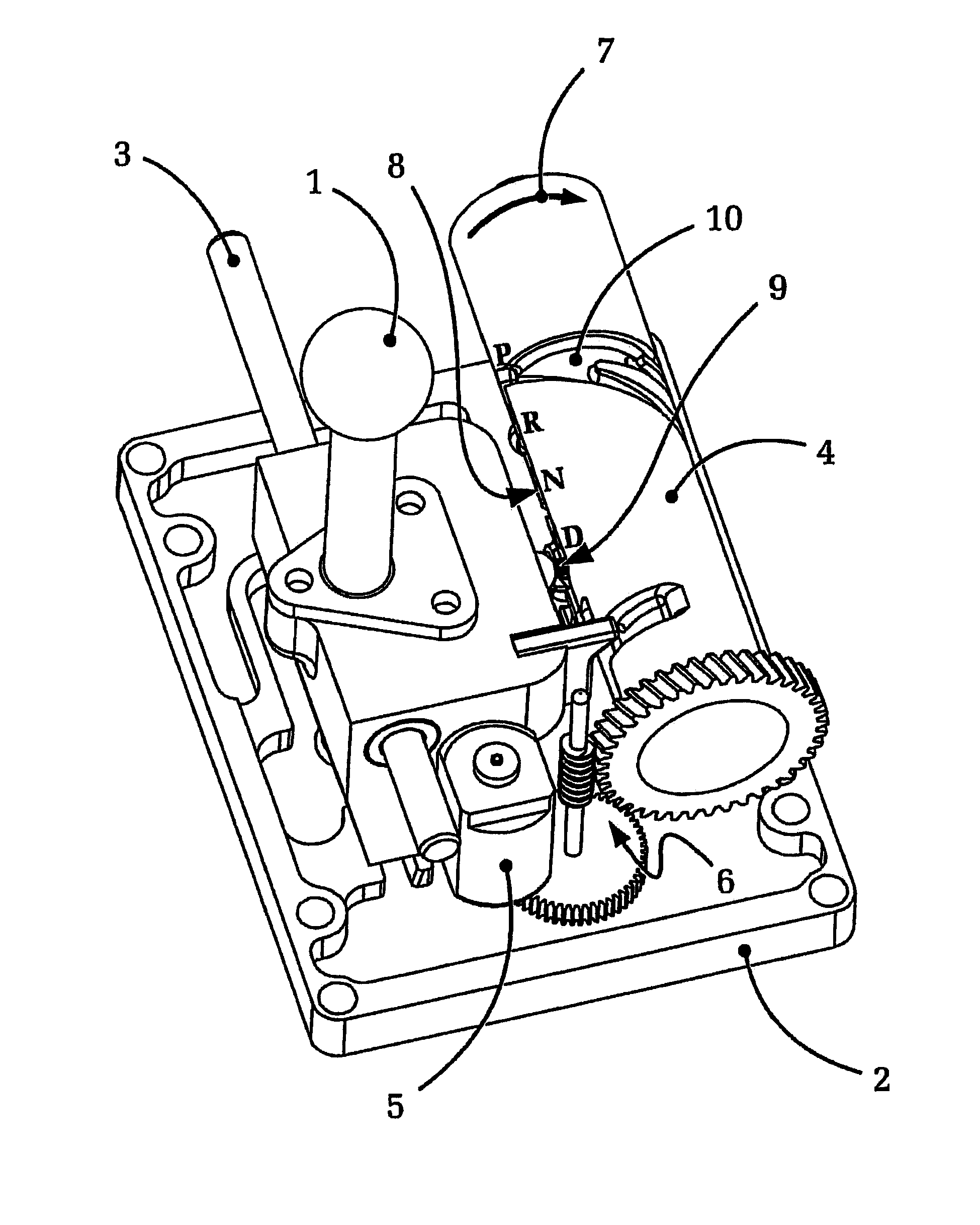
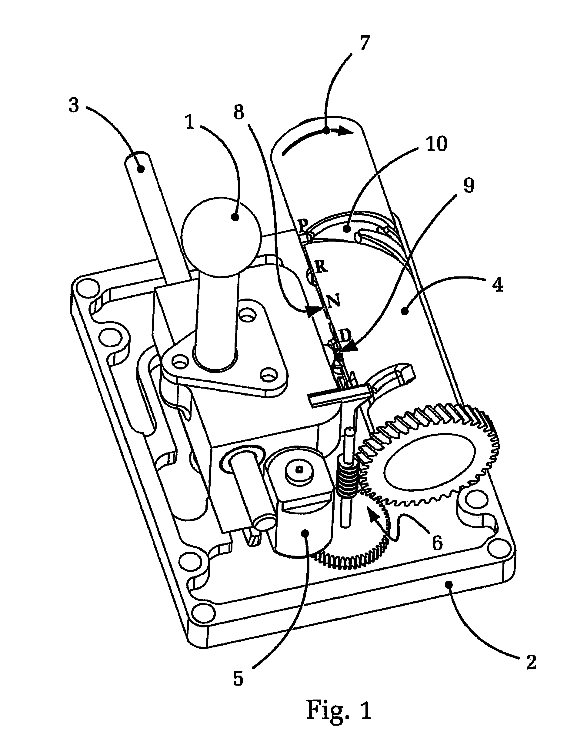
[0043]FIG. 1 shows, in a schematic, isometric depiction, one embodiment of an actuating device according to the present invention. The illustration clearly shows a selector lever 1 and base 2 of the actuating device with bearing shaft 3, disposed thereon, for selector lever 1, and a gate shaft 4 that is likewise disposed on base 2. Gate shaft 4 can be rotated about its longitudinal axis, in arrow direction 7, using a servomotor 5 having a worm gear pair 6.

[0044]Notched gate 8, which is disposed on the gate shaft 7 in FIG. 1 in the “9 o'clock” position, for selector lever 1 is barely visible in FIG. 1, as is detent pin 9 which is engaged in notched gate 8; detent pin 9 is disposed in a (not-depicted) guide that is connected to selector lever 1 and is spring-loaded on selector lever 1.

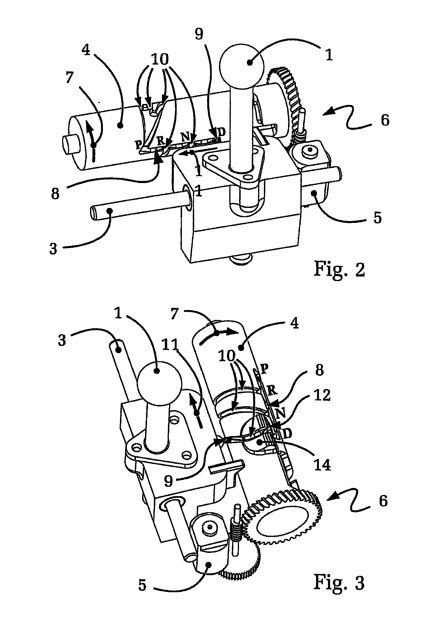
[0045]Notched gate 8, which is disposed on or recessed in gate shaft 4, is more clearly visible in FIG. 2. The illustration shows that, in this position (which corresponds to the position of gate shaft 4...


PUM


Abstract

An actuating device for a gear shifting transmission. The actuating device includes a selector lever which has stable selector lever positions, and a detent mechanism with a detent element and notched gate, the detent element is connected to the selector lever. The notched gate is disposed on a gate shaft that rotates when actuated. The gate shaft includes at least one helical return groove for the detent element. Due to rotation of the gate shaft, the detent element can be transferred from a start position, along the return groove, into a target position. The selector lever position always reflects the actual gear stage of the transmission, even with shift-by-wire-controlled gear shifting transmissions. The driver is provided with reliable visual and tactile feedback about the gear state of the transmission. The actuating device is structurally reliable, has low energy consumption, produces minimal noise, and requires minimal construction space.

Description

[0001]This application is a National Stage completion of PCT / DE2008 / 050035 filed Dec. 4, 2008, which claims priority from German patent application serial no. 10 2007 058 922.2 filed Dec. 5, 2007.FIELD OF THE INVENTION[0002]The invention relates to an actuating device for a gear shifting transmission, e.g. for an automatic transmission having shift-by-wire actuation.BACKGROUND OF THE INVENTION[0003]Gear shifting transmissions of motor vehicles are usually controlled or shifted using an actuating device disposed within reach of the driver. Actuating elements such as shift levers or selector levers are used customarily for this purpose, and are disposed between the front seats of the motor vehicle, for example.[0004]The structural and ergonomic requirements on actuating devices of this type for gear shifting transmissions are diverse. For example, to provide the driver with a realistic feel for the actuation of the transmission for reasons of safety and ergonomics, a requirement of ac...

Claims


Application Information

Patent Timeline
IPC IPC(8): F16H59/04F16H63/08
CPCF16H59/10F16H61/24F16H2061/241Y10T74/2011Y10T74/2014Y10T74/20018F16H2059/0239
Inventor GIEFER, ANDREASRAKE, LUDGER
Owner ZF FRIEDRICHSHAFEN AG
Why Eureka
Try Eureka