Internal Combustion Engines

a combustion engine and combustion chamber technology, applied in the direction of reciprocating combination engines, electric control, combustion-air/fuel-air treatment, etc., can solve the problems of noisy and slow combustion of reciprocating piston compression ignition engines

Active Publication Date: 2010-12-09
ROSEN IAN KURT
View PDF30 Cites 24 Cited by
  • Summary
  • Abstract
  • Description
  • Claims
  • Application Information

AI Technical Summary

Problems solved by technology

Historically, reciprocating piston compression ignition engines were considered noisy and slow and in the automotive field were used mainly for trucks and other commercial vehicles such as buses.

Method used


Image

  • Internal Combustion Engines
  • Internal Combustion Engines
  • Internal Combustion Engines

Examples


Embodiment Construction

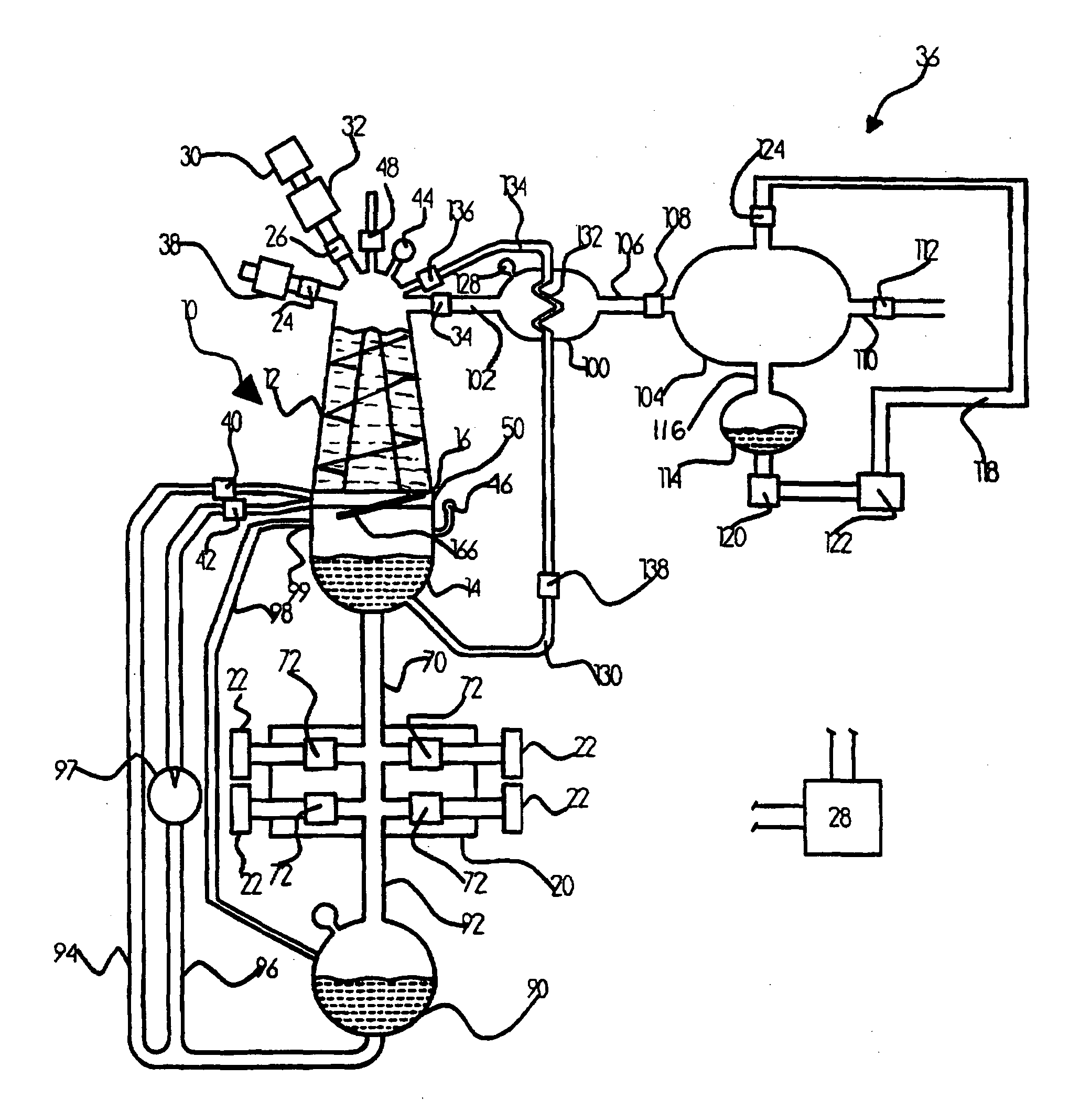
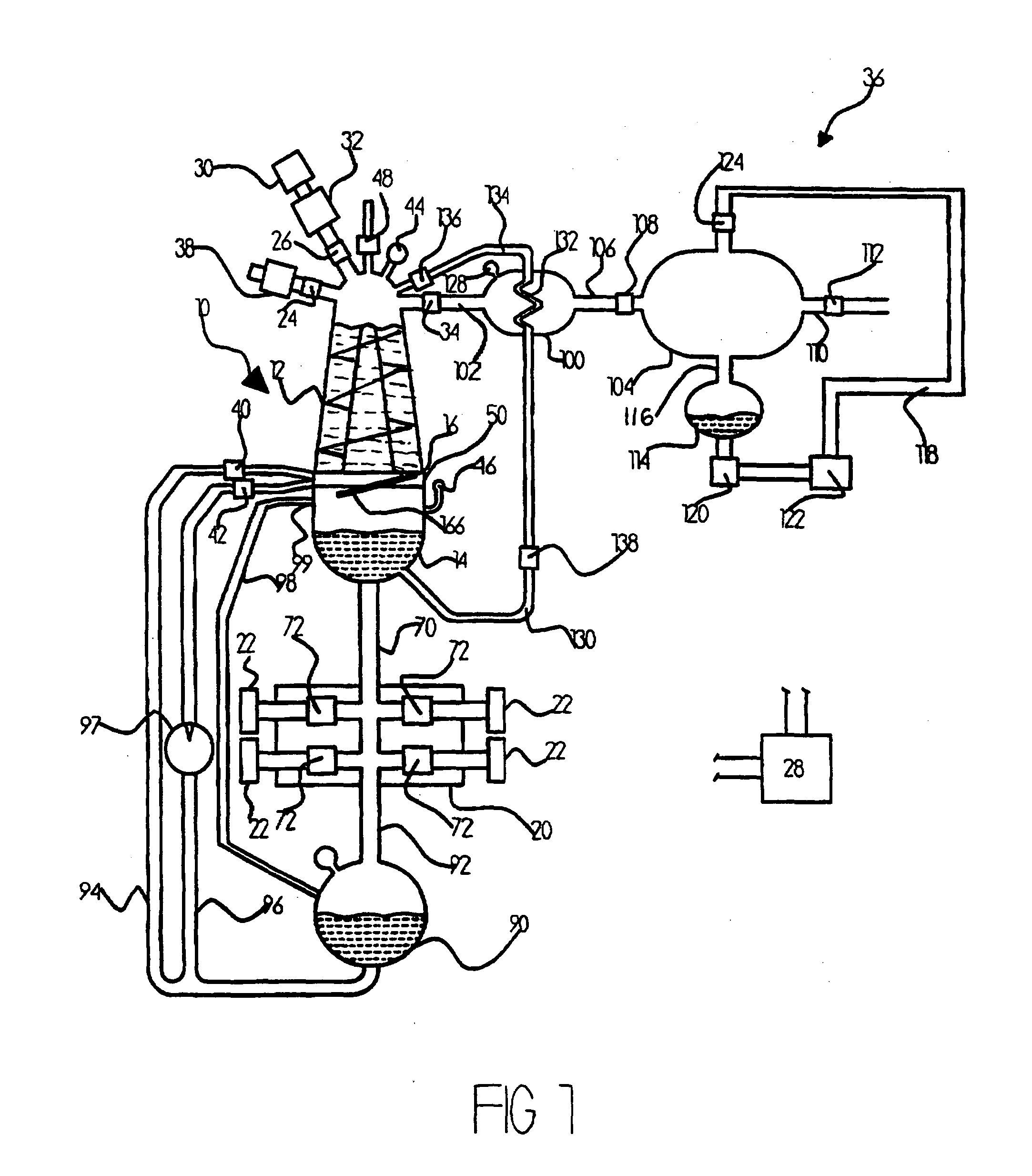
[0054]Referring to FIG. 1, an internal combustion engine 10 comprises a single combustion chamber in the form of a closed cylinder 12 that is connected with a first reservoir 14 via outlet valving 16. The cylinder 12 has an inlet end region at which constituents of a combustible mixture are selectively admitted to the cylinder and an outlet end region, which is where the outlet valving 16 is located. The combustible mixture is combusted in the cylinder 12 to produce pressure increases in the cylinder and the outlet valving 16 is operable to release an outflow of liquid from the cylinder under the influence of those pressure increases as the main energy output of the cylinder.

[0055]The first reservoir 14 is disposed generally below the cylinder 12 at the outlet end region of the cylinder to receive the outflow of energised liquid and stores the energy output until required. The liquid stored in the first reservoir 14 is supplied on demand to a drive unit 20 of a motor vehicle drive t...


PUM


Abstract

An internal combustion engine (10) comprises a chamber (12), inlet valving (24, 26) operable to admit constituents of a combustible mixture into the chamber for combustion in the chamber to provide a pressure increase in the chamber, outlet valving (16) operable to release an outflow of liquid from the chamber under the influence of that pressure increase as an energy output of the chamber, input valving (136) for selectively admitting a heated aqueous fluid into chamber and a supply system (130, 132, 134) for supplying heated aqueous fluid to the input valving. The input valving is arranged to admit the heated aqueous fluid into a region of the chamber in which combustion of the combustible mixture occurs such that at least a portion of the heated aqueous fluid will dissociate to provide hydrogen that is combusted in the chamber.

Description

FIELD OF THE INVENTION[0001]The invention relates to internal combustion engines and particularly, but not exclusively, to internal combustion engines for powering automotive vehicles.BACKGROUND TO THE INVENTION[0002]The reciprocating piston spark ignition engine is one known form of internal combustion engine used to power automotive vehicles. Reciprocating piston spark ignition engines comprise a number of pistons arranged to reciprocate in respective cylinders and each connected to a crankshaft. Each of the cylinders is provided with inlet valving for controlling the inflow of air and fuel, exhaust valving for controlling the exhaust of the products of combustion and a spark plug for igniting the air fuel mixture. Where the supply of fuel to the engine is controlled by a carburetor, the air and fuel are mixed in an intake manifold upstream of the cylinders and the inlet valving comprises an intake valve that controls the intake of the fuel-air mixture into the cylinder. If the fu...

Claims


Application Information

Patent Timeline
Patent Type & Authority Applications(United States)
IPC IPC(8): F02B43/08
CPCF01B21/00F01K15/02F01K21/04F01N5/02F02M27/02F02M21/0287F02M21/0206F02M31/02F02D41/0027F02B61/00F02B43/12F02B43/10F02M21/023F02B71/045F02B47/02F02G5/00F02B21/00F02B75/00F04F1/16F01K25/06Y02T10/12Y02T10/30
Inventor BUCHANAN
Owner ROSEN IAN KURT
Why Eureka
Try Eureka