Non-Pneumatic Elastic Wheel

a non-pneumatic, elastic wheel technology, applied in the field of laminated products, can solve the problems of inability to use, risk of localized buckling of the shear band level with the membrane, and inability to flex and/or compress the force, and achieve high endurance, non-hysteretic effect, and high resistance to flexural and/or compressive stress

Active Publication Date: 2010-12-09
MICHELIN RECH & TECH SA +1
View PDF35 Cites 48 Cited by
  • Summary
  • Abstract
  • Description
  • Claims
  • Application Information

AI Technical Summary

Benefits of technology

[0018]This non-pneumatic resilient wheel of the invention has a highly aerated deformable cellular structure, which has proved to exhibit, unexpectedly, a high resistance to flexural and / or compressive stresses and a high endurance to such repeated or alternated stresses. It has the advantage of being non-hysteretic.

Problems solved by technology

Firstly, at the customary operating temperatures, for example between −30° C. and +40° C., it is relatively hysteretic, that is to say that some of the energy supplied for rolling is dissipated (lost) in the form of heat. Next, for significantly lower operating temperatures, such as those that can be found, for example in geographical areas of polar type, typically below −50° C. or even less, it is well known that rubber rapidly becomes brittle, frangible and therefore unusable. Under such extreme conditions, it is moreover understood that temperature fluctuations that are more or less sizable and rapid, combined, for example, with relatively high mechanical stresses, could also lead to adhesion problems between the two membranes and the shear layer, with a risk of localized buckling of the shear band level with the membranes and endurance that is in the end degraded.

Method used


Image

  • Non-Pneumatic Elastic Wheel
  • Non-Pneumatic Elastic Wheel
  • Non-Pneumatic Elastic Wheel

Examples


Embodiment Construction

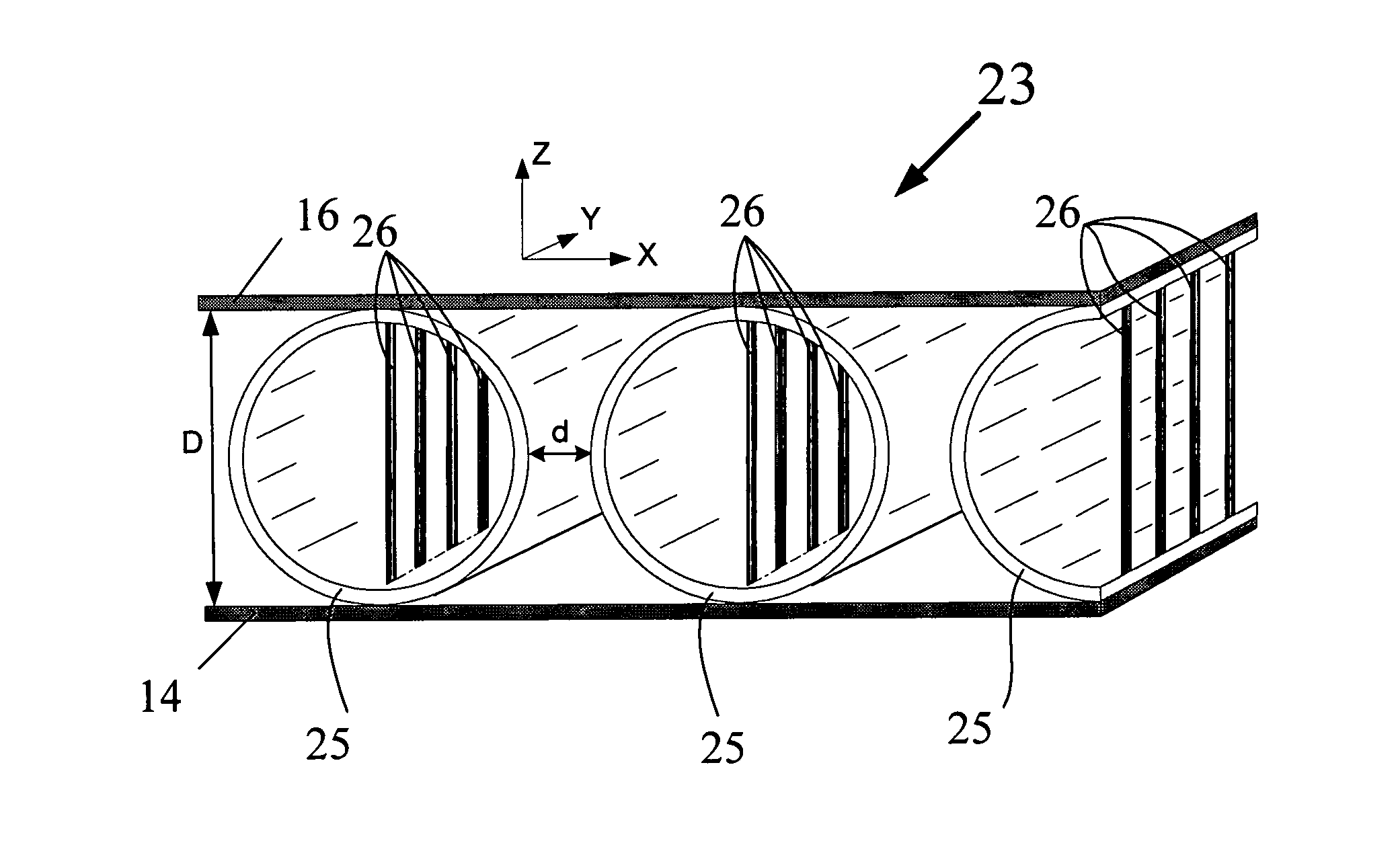
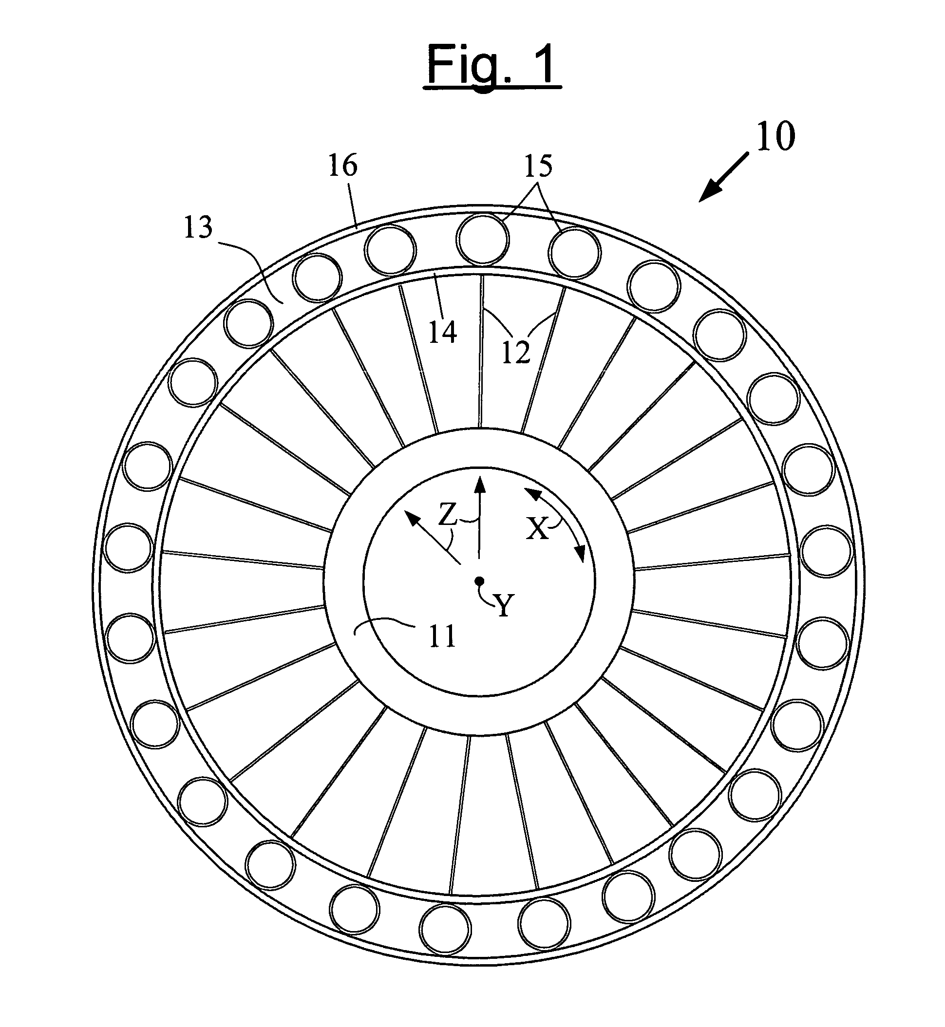
[0042]By way of example, FIG. 1 represents, very schematically, a radial cross section (i.e. in a plane perpendicular to the axis of rotation Y of the wheel) of a non-pneumatic resilient wheel (10) that is structurally supported (i.e. owing to a load-bearing structure), the circumferential shear band (13) of which is constituted by a laminated product.

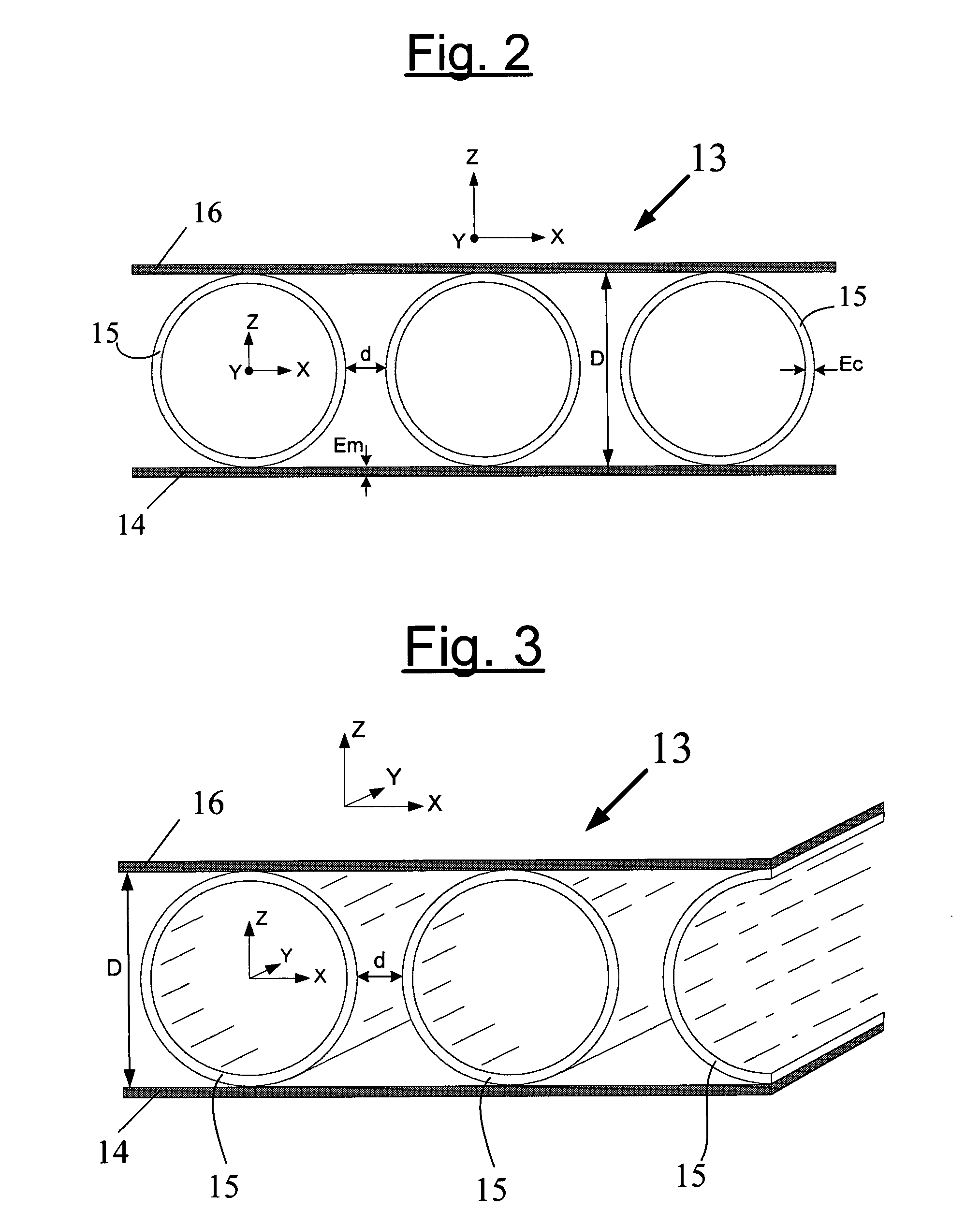
[0043]This wheel, that defines three perpendicular directions, circumferential (X), axial (Y) and radial (Z), has the main feature of comprising at least:[0044]a hub (11);[0045]an annular band referred to as a shear band (13) comprising at least one inner circumferential membrane (14) and one outer circumferential membrane (16) that are oriented in the circumferential direction X; and[0046]a plurality of support elements (12) or “wheel spokes” that connect the hub (11) to the inner circumferential membrane (14),

and it is characterized in that[0047]the two membranes (14, 16) are connected to one another by means of a series, that extend...


PUM


Abstract

Non-pneumatic resilient wheel (10), that is supported structurally and defines three perpendicular directions, circumferential (X), axial (Y) and radial (Z), this wheel comprising: a hub (11); an annular band referred to as a shear band (13) comprising at least one inner circumferential membrane (14) and one outer circumferential membrane (16) that are oriented in the circumferential direction X; and a plurality of support elements (12) that connect the hub (11) to the inner circumferential membrane (14)U. The two membranes (14, 16) are connected to one another by means of a series, that extends in the circumferential direction (X), of cylinders (15) referred to as connection cylinders, said connection cylinders (15) being non-touching in the circumferential direction X and having their generatrix oriented in the axial direction Y. The connection cylinders (15) are composite cylinders comprising fibres embedded in a resin matrix.

Description

FIELD OF THE INVENTION[0001]The present invention relates to laminated products, that is to say to products made of several layers or bands of planar or non-planar form, which are joined together, for example of the cellular or honeycomb type.[0002]The invention relates more particularly to resilient (flexible) wheels for motor vehicles of the “non-pneumatic” type: that is to say that do not require inflation gases such as air in order to assume their usable form, and to the incorporation in such wheels of composite laminated products, all or part of which is constituted of fibres coated in a resin matrix.PRIOR ART[0003]Non-pneumatic flexible wheels or tires are well known to a person skilled in the art. They have been described in a great number of patent documents, for example in patents or patent applications EP 1 242 254 (or U.S. Pat. No. 6,769,465), EP 1 359 028 (or U.S. Pat. No. 6,994,135), EP 1 242 254 (or U.S. Pat. No. 6,769,465), U.S. Pat. No. 7,201,194, WO 00 / 37269 (or U.S...

Claims


Application Information

Patent Timeline
Patent Type & Authority Applications(United States)
IPC IPC(8): B60C7/00
CPCB60C7/18B60B5/02B60B9/26Y10T152/10306B60C7/22B60B9/00
Inventor DELFINO, ANTONIOMERALDI, JEAN-PAULPOZO, FRANCOIS
Owner MICHELIN RECH & TECH SA
Why Eureka
Try Eureka