Systems and devices for determining weld cable inductance

a technology of inductance and system, applied in the direction of welding equipment, arc welding equipment, manufacturing tools, etc., can solve the problems of inability to adequately handle the dynamic requirements of a switched-mode welding power supply, analog controllers are often associated, and analog controllers often fall short of responding quickly enough to quickly occurring events

Active Publication Date: 2010-12-09
ILLINOIS TOOL WORKS INC
View PDF23 Cites 82 Cited by
  • Summary
  • Abstract
  • Description
  • Claims
  • Application Information

AI Technical Summary

Benefits of technology

[0005]In an embodiment, a welding power supply includes power conversion circuitry including one or more power semiconductor switches adapted to receive power from a primary source and to switch the one or more power semiconductor switches between an ON configuration and an OFF configuration to convert the received power to a welding output. The welding power supply also includes a controller adapted to determine a weld cable inductance during a welding operation by measuring a peak to peak switching ripple generated by the switching of the power semiconductor switches in a voltage present on welding output terminals.

Problems solved by technology

Unfortunately, analog controllers are often associated with drawbacks, such as the inability to adequately handle the dynamic requirements of a switched-mode welding power supply.
For example, analog controllers often fall short of responding quickly enough to quickly occurring events in a welding arc, may happen with time intervals of less than 1 mSec.

Method used


Image

  • Systems and devices for determining weld cable inductance
  • Systems and devices for determining weld cable inductance
  • Systems and devices for determining weld cable inductance

Examples


Embodiment Construction

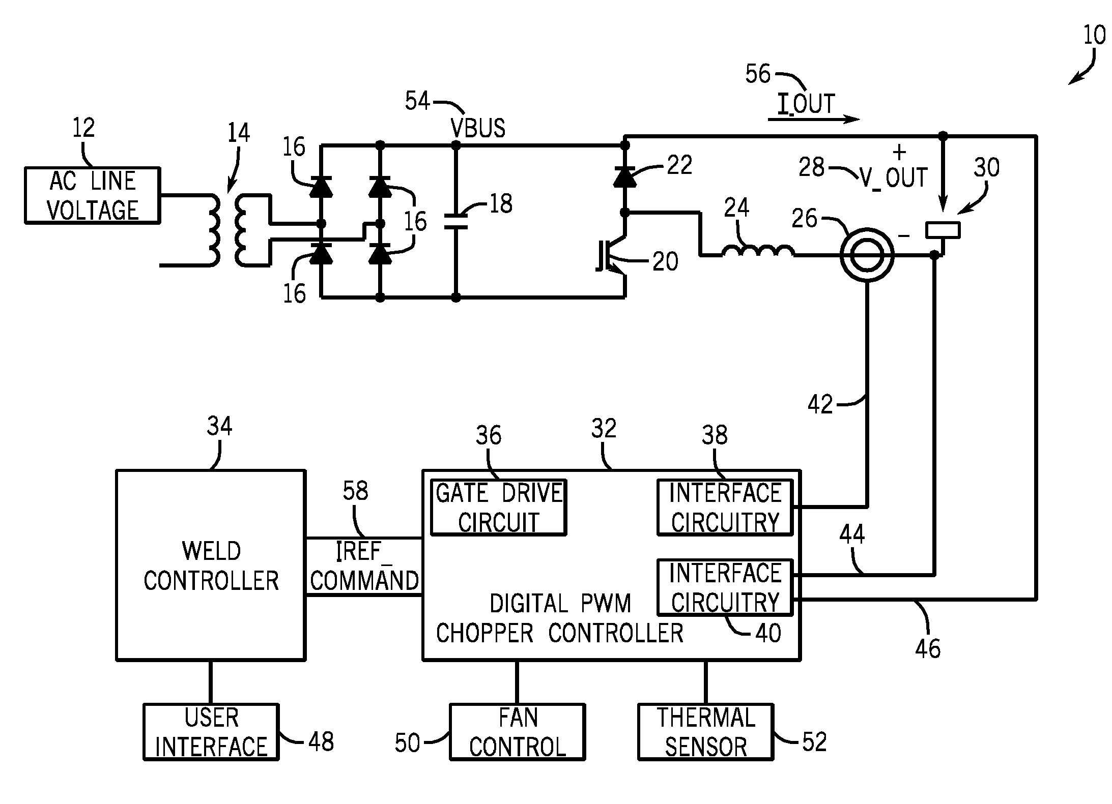
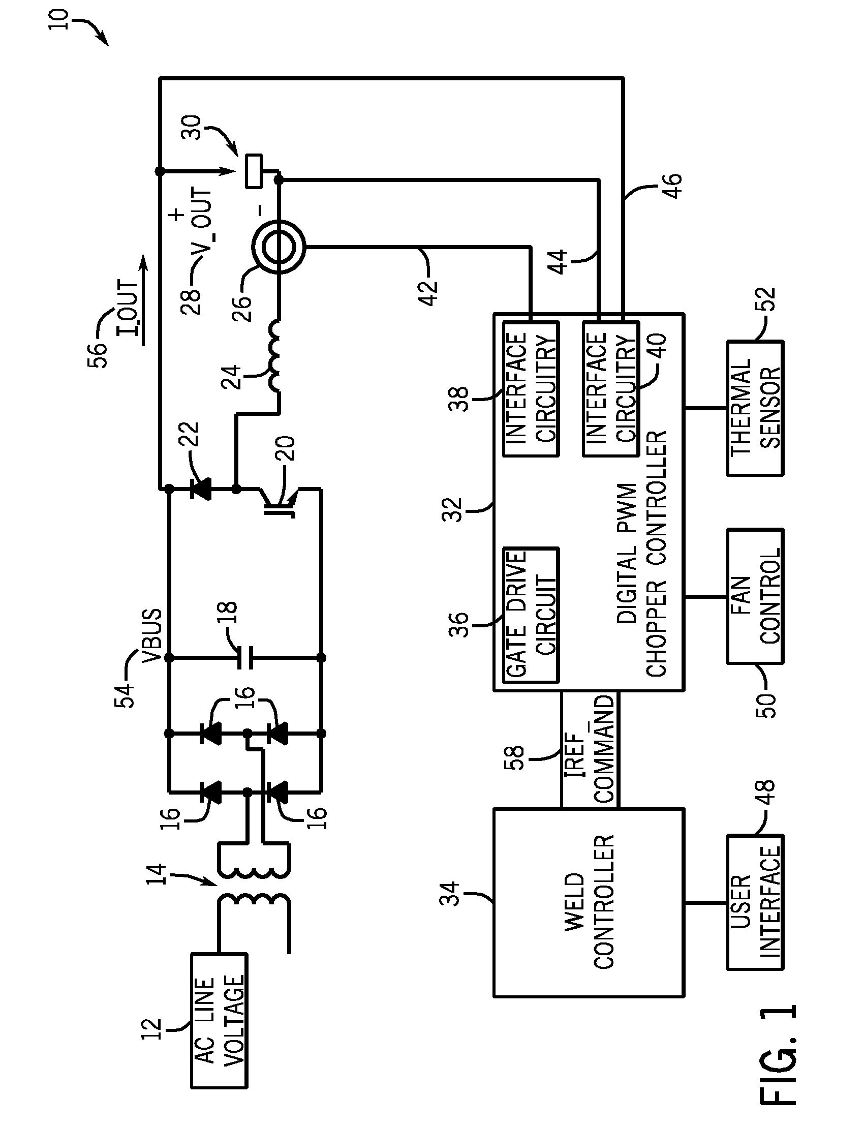
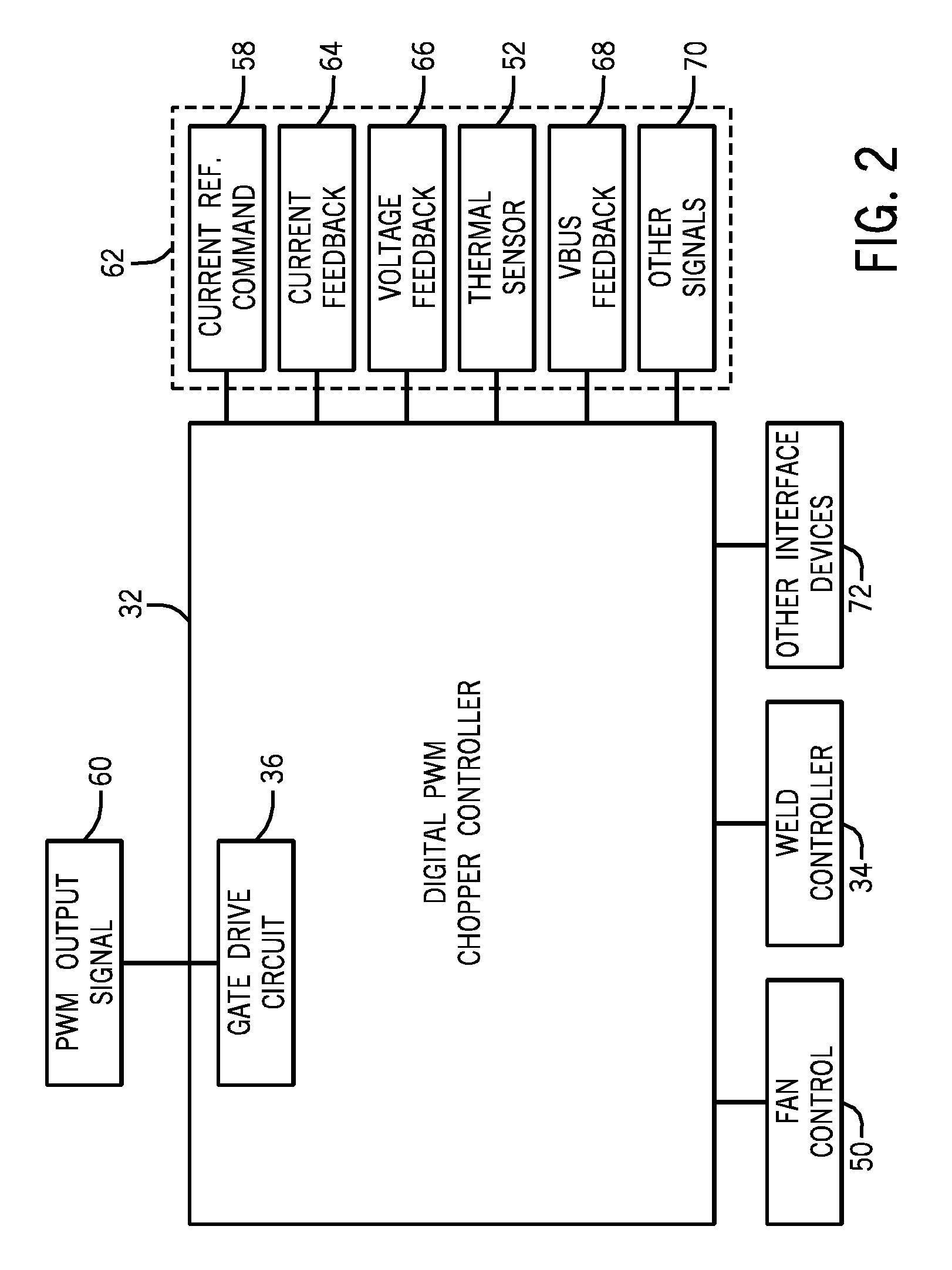
[0022]FIG. 1 illustrates an exemplary chopper circuit 10 configured to function as a switched-mode welding power supply 10. The chopper circuit 10 includes an AC line voltage input 12, a transformer 14, a set of diodes 16, a capacitor 18, a power semiconductor switch 20, a diode 22, an inductor 24, a current sensor 26, an output voltage 28, and a welding arc 30. The chopper circuit 10 is controlled by a digital pulse width modulated (PWM) chopper controller 32 coupled to a weld controller 34. The digital controller 32 includes gate drive circuitry 36 configured to switch the power semiconductor switch 200N and OFF and interface circuitry 38, 40 configured to receive current and voltage feedback from feedback connections 42, 44, and 46. The weld controller 34 and / or the digital controller 32 may be coupled to a variety of inputs and outputs, such as the illustrated user interface 48, fan control 50, and thermal sensor 52.

[0023]During operation, the AC line voltage 12 is received by t...


PUM

PropertyMeasurementUnit
voltageaaaaaaaaaa
poweraaaaaaaaaa
inductanceaaaaaaaaaa

Abstract

Systems, devices, and methods for measuring a peak to peak switching ripple in a voltage present on welding output terminals are provided. The systems, devices, and methods may also be utilized to determine, during a welding operation, a weld cable inductance based on the measured peak to peak voltage ripple.

Description

CROSS REFERENCE TO RELATED APPLICATIONS[0001]This application is a Non-Provisional patent application of U.S. Provisional Patent Application No. 61 / 183,731, entitled “Welding Power Supply with Digital Control”, filed Jun. 3, 2009, which is herein incorporated by reference.BACKGROUND[0002]The invention relates generally to welding power supplies, and, more particularly, to a digital controller for a switched mode welding power supply.[0003]Many types of welding power supplies capable of providing a welding power output from an alternating current (AC) or a direct current (DC) source of power have been developed. One such type of welding power supply is a switched-mode power supply, which utilizes power semiconductor switches to chop a DC source of power and convert the chopped power to a voltage and / or current suitable for welding. Switched-mode power supplies such as inverter type power supplies and chopper type power supplies have been developed to meet the needs of various welding...

Claims


Application Information

Patent Timeline
Patent Type & Authority Applications(United States)
IPC IPC(8): B23K9/10
CPCB23K9/0953B23K9/0956B23K9/1062
Inventor VOGEL, BERNARD J.
Owner ILLINOIS TOOL WORKS INC
Why Eureka
Try Eureka