Methods and devices for leakage current reduction

Active Publication Date: 2010-12-09
PSEMI CORP
View PDF13 Cites 44 Cited by
  • Summary
  • Abstract
  • Description
  • Claims
  • Application Information

AI Technical Summary

Benefits of technology

[0015]According to a first aspect of the present teachings, an arrangement for reducing leakage current in a regulator transistor is provided, comprising: a first regulator transistor biased by an input voltage; a second regulator transistor connected with the first regulator transistor and biased by a first voltage so

Problems solved by technology

However, when MOS transistors having a low threshold voltage are used in a regulator, and the MOST transistors are operated in an OFF state, they may have a higher leakage current from source to drain because they are still in a subthreshold operation when the gate-to-source voltage (Vgs) is equal to zero.
How

Method used


Image

  • Methods and devices for leakage current reduction
  • Methods and devices for leakage current reduction
  • Methods and devices for leakage current reduction

Examples


Example

[0027]Like reference numbers and designations in the various drawings indicate like elements.

DETAILED DESCRIPTION

[0028]Throughout this description, embodiments and variations are described for the purpose of illustrating uses and implementations of the inventive concept. The illustrative description should be understood as presenting examples of the inventive concept, rather than as limiting the scope of the concept as disclosed herein.

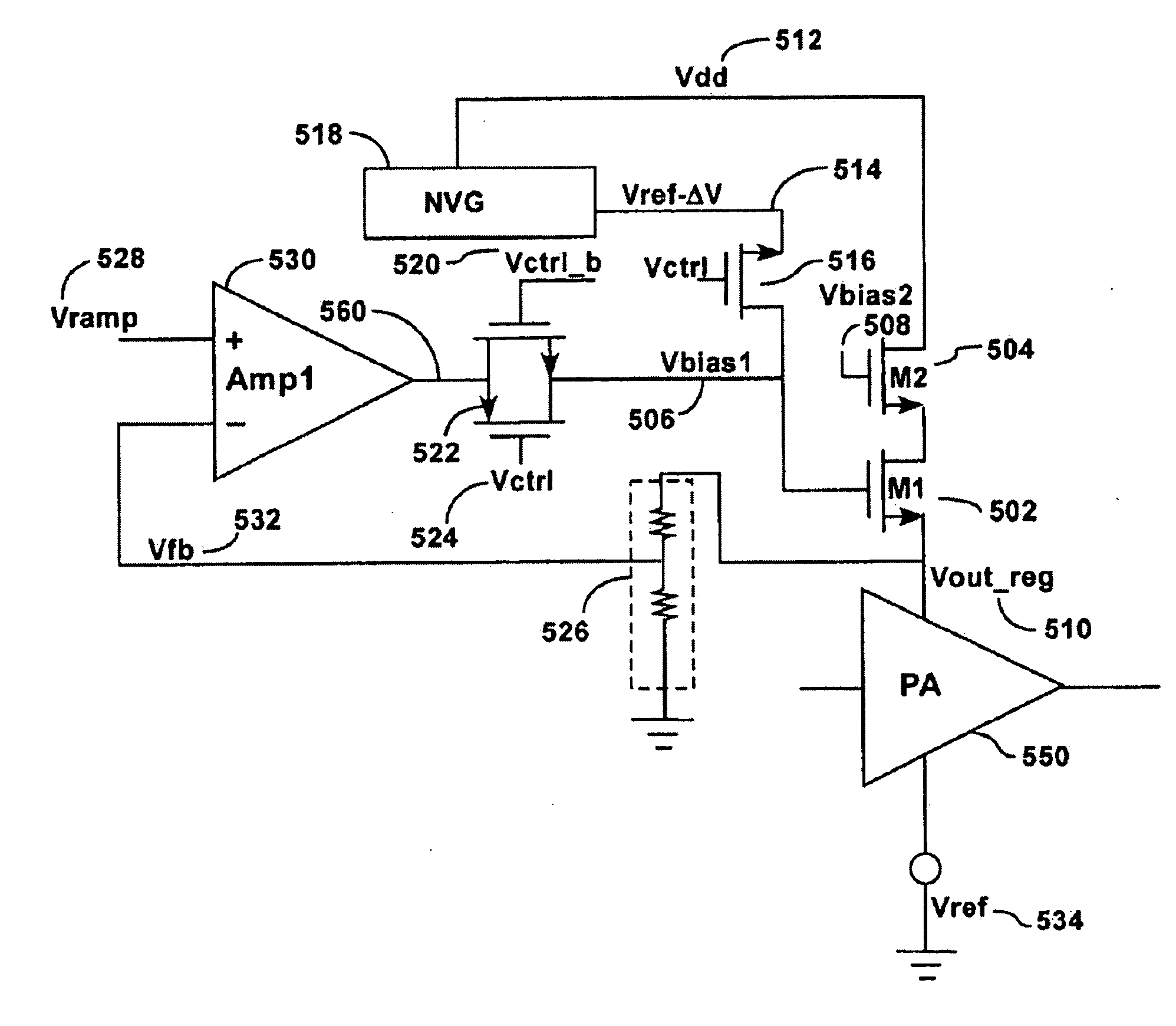
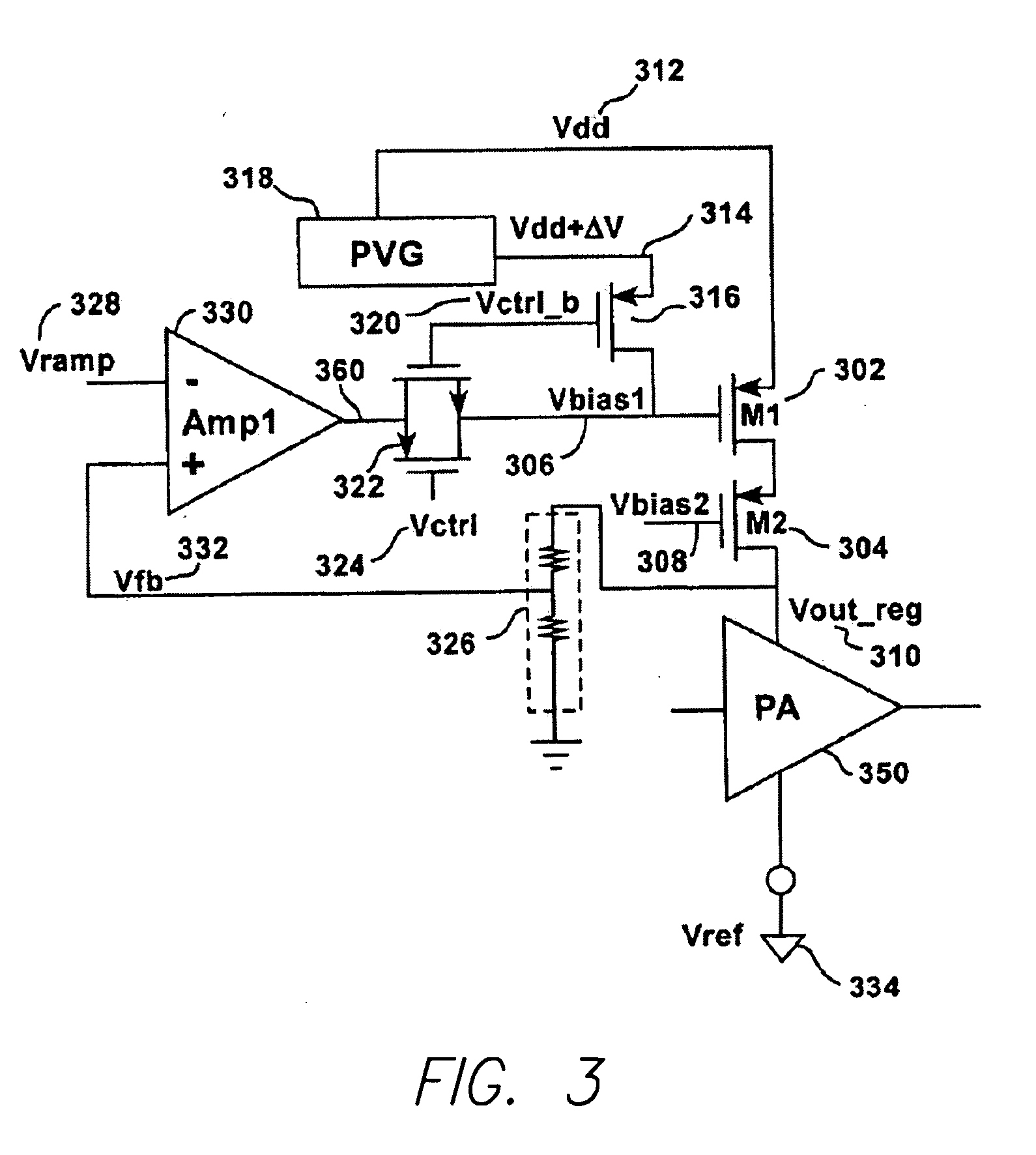
[0029]FIG. 3 shows a circuital arrangement according to an embodiment of the present disclosure. In particular, FIG. 3 shows a simplified block diagram of a power amplifier PA (350) with regulator transistors M1 (302) and M2 (304). In addition to the power amplifier and regulator transistor shown in FIG. 2, a positive voltage generator block PVG (318) and switching logic (316, 320, 322, 324) are included in the circuit of FIG. 3 as shown.

[0030]According to the embodiment of FIG. 3, a gate input voltage (306) of a p-channel regulator transistor M1 (302...


PUM


Abstract

Methods and devices for leakage current reduction are described. A regulator transistor is connected to a switch to bias the transistor with a first voltage during an ON state and a second voltage during the OFF state of the transistor. The switchable bias allows leakage current decrease and “on” resistance increase of the transistor.

Description

CROSS REFERENCE TO RELATED APPLICATIONS[0001]The present application is a continuation-in-part of U.S. patent application Ser. No. 12 / 455,671 filed on Jun. 3, 2009 for “Leakage Current Reduction in a Power Regulator”, incorporated herein by reference in its entirety.BACKGROUND[0002]1. Field[0003]The present teachings relate to leakage current reduction. More particularly, the present teachings relates to methods and devices for leakage current reduction.[0004]2. Description of Related Art[0005]Mobile communication devices such as mobile telephones are generally powered by batteries. Therefore, it is desirable to improve the time before the battery charge is depleted. One method of improving battery life is to reduce the unintended current leakage from power supply to electrical ground or other reference voltage in the radio. By reducing this wasted current, the useful battery time is increased. Integrated circuit power amplifiers often have a regulator function that adjusts the outp...

Claims


Application Information

Patent Timeline
IPC IPC(8): H03F1/34H03K3/01H03F3/04
CPCG05F1/56H03F1/0244H03F2200/507H03F2200/357H03F1/0261
Inventor ADAMSKI, JAROSLAWLOSSER, DANIELSHARMA, VIKAS
Owner PSEMI CORP
Why Eureka
Try Eureka