Shift register and a liquid crystal display device having the same

a technology of shift register and liquid crystal display device, which is applied in the direction of digital storage, instruments, computing, etc., can solve the problem that the gate driving signal gs(n) may not reach the ideal voltage level

Active Publication Date: 2010-12-09
AU OPTRONICS CORP
View PDF6 Cites 46 Cited by
  • Summary
  • Abstract
  • Description
  • Claims
  • Application Information

AI Technical Summary

Problems solved by technology

As a result, the gate driving signal GS(n) may not be able to reach ideal voltage level.

Method used


Image

  • Shift register and a liquid crystal display device having the same
  • Shift register and a liquid crystal display device having the same
  • Shift register and a liquid crystal display device having the same

Examples


Embodiment Construction

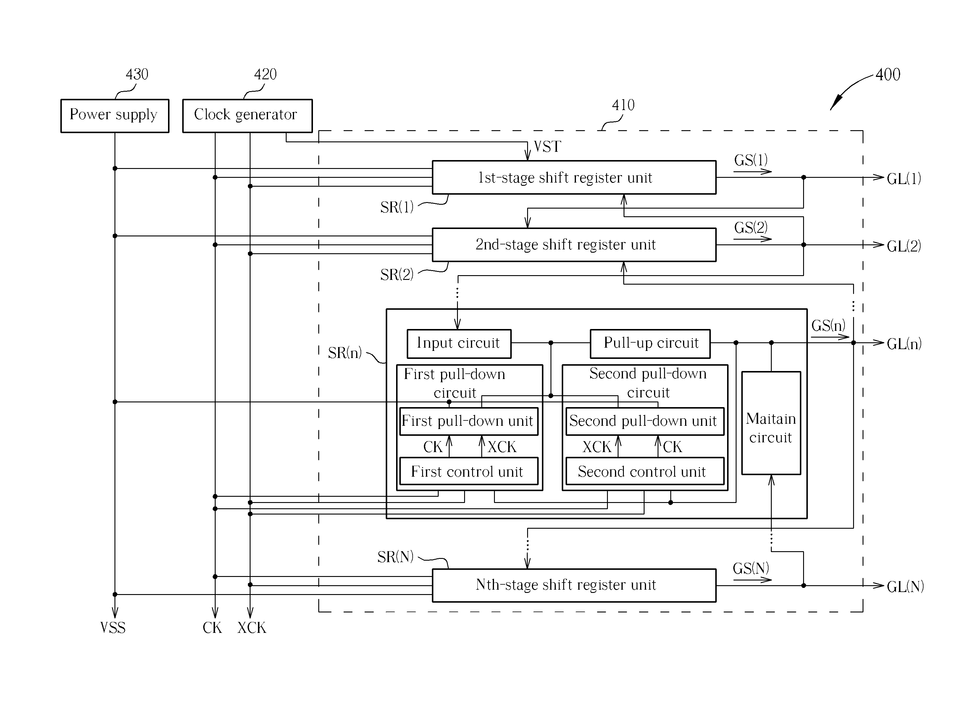
[0023]Reference is made to FIG. 4 for a simplified block diagram of an LCD device 400 according to the present invention. FIG. 4 only illustrates partial structure of the LCD 400, including a plurality of gate lines GL(1)-GL(N), a shift register 410, a clock generator 420, and a power supply 430. For operating the shift register 410, the clock generator 420 provides a start pulse signal VST and two clock signals CK and XCK, while the power supply 430 provides a bias voltage VSS. The clock signals CK and XCK periodically switch between a high voltage level and a low voltage level, and have opposite phases at the same time. The high and low voltage levels of the clock signals CK and XCK are represented by VGH and VGL, wherein VGL is lower than VSS.

[0024]The shift register 410 includes N shift register units SR(1)-SR(N) each having output ends respectively coupled to the corresponding gate lines GL (1)-GL(N), wherein N is a positive integer greater than or equal to 3. According to the ...


PUM


Abstract

A shift register of an LCD device operates based on two clock signals and maintains the gate voltage of an output transistor switch using two pull-down transistor switches. The gate voltages of the pull-down transistor switches are switched periodically between the high and low level of the clock signals. During the output period, the transistor switches have negative gate-source voltages so as to reduce leakage.

Description

BACKGROUND OF THE INVENTION[0001]1. Field of the Invention[0002]The present invention is related to a shift register of an LCD device, and more particularly, to a shift register of an LCD device which reduces leakage.[0003]2. Description of the Prior Art[0004]Liquid crystal display (LCD) devices, characterized in low radiation, thin appearance and low power consumption, have gradually replaced traditional cathode ray tube (CRT) displays and been widely used in electronic products, such as personal digital assistants (PDAs), flat-panel televisions or mobile phones. Traditional LCD devices display images by driving the pixels of the panel using external chips. Recently, the GOA technique, in which the driving circuits are directly fabricated on the LCD panel, has been developed in order to reduce the number of devices and to lower manufacturing costs.[0005]Reference is made to FIG. 1 for a simplified block diagram of a prior art LCD device 100. FIG. 1 only illustrates partial structur...

Claims


Application Information

Patent Timeline
Patent Type & Authority Applications(United States)
IPC IPC(8): G09G3/36G11C19/00
CPCG11C19/28G09G3/3677
Inventor HSU, JE-HAOCHEN, WEN-PINYU, CHIU-MEICHANG, LEE-HSUN
Owner AU OPTRONICS CORP
Why Eureka
Try Eureka