Mobile terminal and network node
- Summary
- Abstract
- Description
- Claims
- Application Information
AI Technical Summary
Benefits of technology
Problems solved by technology
Method used
Image

Examples
first embodiment
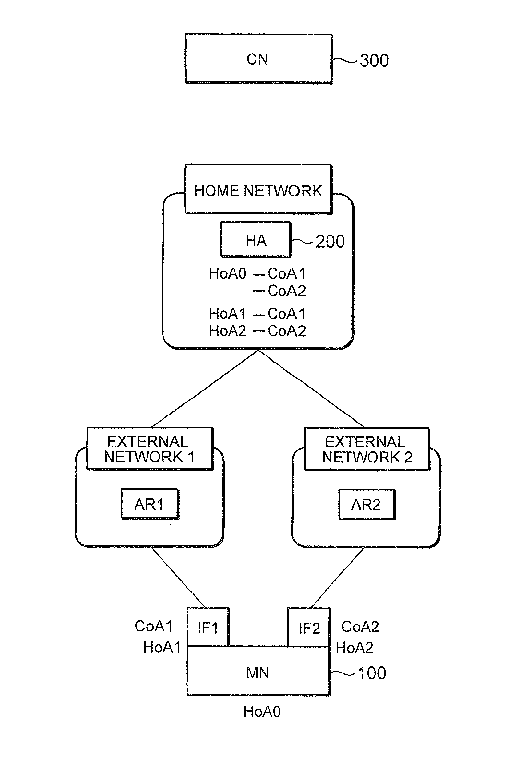
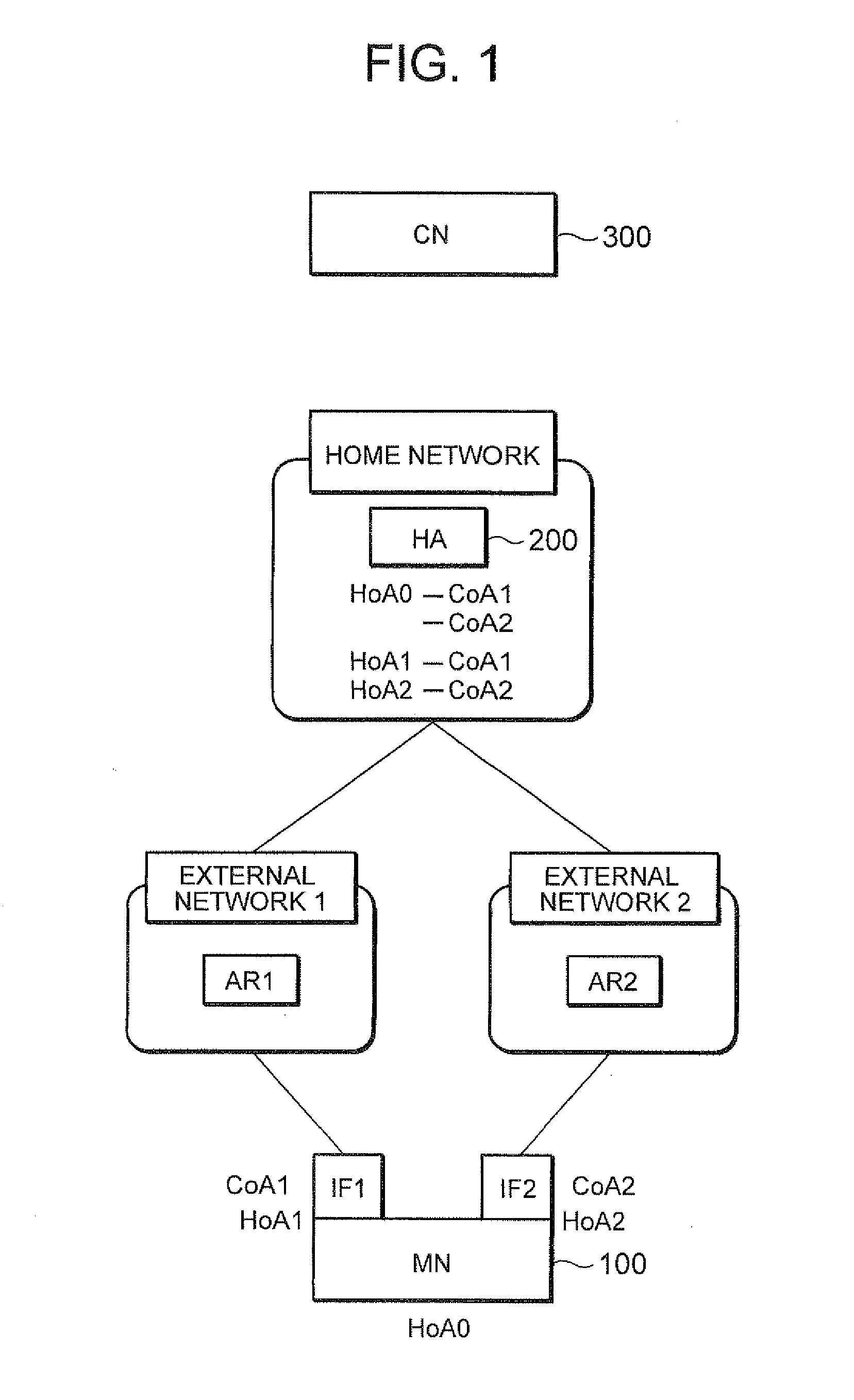
[0080]A first embodiment of the present invention will first be described. FIG. 1 is a diagram showing the structure of a network according to the first embodiment of the present invention. In FIG. 1, a MN 100 has two interfaces (hereinafter referred to as IF1 and IF2), and communicates with a CN 300. The IF1 of the MN 100 is connected to an access router (AR1) of an external network 1 and assigned CoA1. On the other hand, IF2 of the MN 100 is connected to an access router (AR2) of an external network 2 and assigned CoA2.
[0081]Also shown in FIG. 1 is a home network of the MN 100. This home network has a HA 200 for managing location information on the MN 100. The external networks 1 and 2 are different networks. The MN 100 registers with the HA 200 location information for associating both of CoA1 and CoA2 with a home address (HoA0) of the MN 100, so that binding information in which the two CoAs, CoA1 and CoA2, are associated with HoA0 is registered with the HA 200. For example, in ...
second embodiment
[0162]A second embodiment of the present invention will next be described. The aforementioned first embodiment of the present invention is such that the HA 200 assigns a HoA exclusively for an interface and the MN 100 requests the HA 200 to assign the dedicated HoA. On the other hand, the second embodiment of the present invention is such that the MN 100 itself generates this dedicated HoA and notifies the HA of the dedicated CoA generated by the MN 100 itself using a BU message sent by the MN 100 upon registering a CoA of each interface.
[0163]In the second embodiment of the present invention, the basic network configuration is the same as that in FIG. 1 mentioned above, but the feature of the MN 100 (that the MN 100 itself generates a dedicated HoA) and the feature of the HA 200 (that it does not assign the dedicated HoA) are different from those in the first embodiment of the present invention.
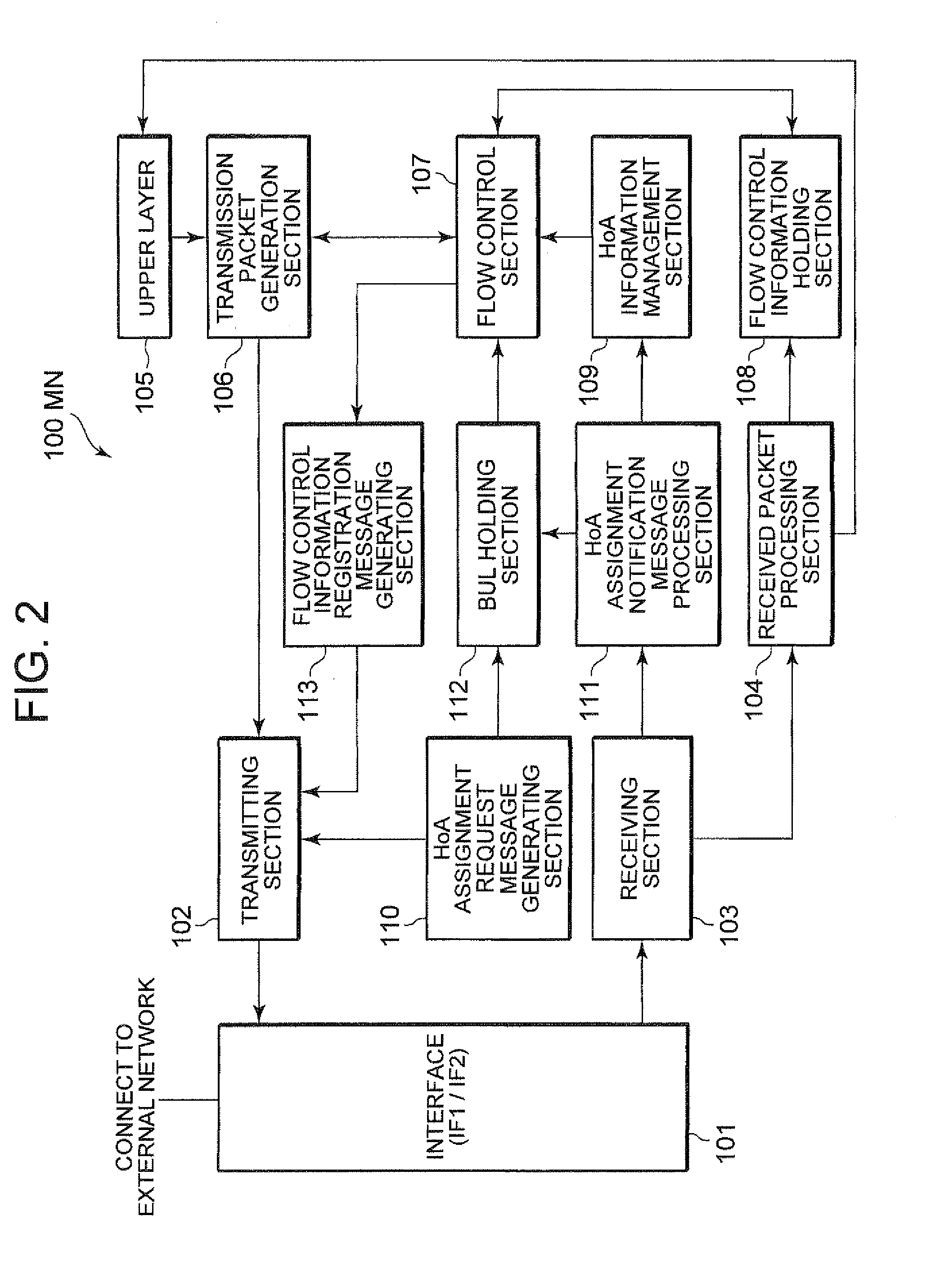
[0164]Next, the configuration of the MN 100 in the second embodiment of the present inve...
third embodiment
[0193]Next, a third embodiment of the present invention will be described. FIG. 21 is a diagram showing the structure of a network according to the third embodiment of the present invention. In FIG. 21, the MN 100 has two interfaces (IF1 and IF2), where IF1 is connected to MAG 1 and assigned address 1, and IF2 is connected to MAG 2 and assigned address 2. The addresses of the MAG 1 and the MAG 2 are associated with a home prefix of the MN 100, and registered with a LMA.
[0194]When the two interfaces of the MN 100 are attached to the same PMIP domain and the same home prefix is advertised from both networks to which the two interfaces are connected, respectively, addresses exclusively for the respective interfaces (corresponding to dedicated HoAs) an address common to the interfaces can be used in the same manner as in the aforementioned first and second embodiments of the present invention.
[0195]The address of each MAG as a CoA for the home prefix is registered with the LMA through a...
PUM
 Abstract
Description
Claims
Application Information
 - R&D
- Intellectual Property
- Life Sciences
- Materials
- Tech Scout
- Unparalleled Data Quality
- Higher Quality Content
- 60% Fewer Hallucinations
Browse by: Latest US Patents, China's latest patents, Technical Efficacy Thesaurus, Application Domain, Technology Topic, Popular Technical Reports.
© 2025 PatSnap. All rights reserved.Legal|Privacy policy|Modern Slavery Act Transparency Statement|Sitemap|About US| Contact US: help@patsnap.com