Optical triangulation

a triangulation and optical technology, applied in the field of optical triangulation, can solve the problem that the analytically derived space-time angle does not account for secondary effects, and achieve the effect of improving quality, and reducing the difficulty of measuremen

Active Publication Date: 2010-12-09
SICK IVP
View PDF3 Cites 5 Cited by
  • Summary
  • Abstract
  • Description
  • Claims
  • Application Information

AI Technical Summary

Benefits of technology

[0042]Thus, using a motion estimation procedure, a direct method of trajectory extension determination is obtained. The method presented above also has the advantage that different trajectories may easily be determined for different areas of the measure images. Furthermore, the method above

Problems solved by technology

Furthermore, the analytically derived space-time angle does not account for secondary effects, su

Method used


Image

  • Optical triangulation
  • Optical triangulation
  • Optical triangulation

Examples


first embodiment

[0094]FIGS. 5A-5C illustrate the determination method of the invention. As may be gleaned from FIG. 5A, the reference object 30 comprises a first portion 32 and a second portion 34, the first and second portions 32, 34 having different reflectance properties. As used herein the expression “reflectance property” relates to a measure of the fraction of incident radiation reflected by a surface. Generally, the “reflectance property” is dependent on inter alia the direction of the reflected light, the direction of the incident light and the wavelength of the incident light. Obviously, the reference object 30 may comprise a plurality of portions, each portion having a reflectance property which is different from the reflectance properties of adjacent portions (not shown).

[0095]In FIG. 5A, the reference object 30 comprises a substantially flat surface in the visual field of the sensor 14 and the surface extends in a direction substantially parallel to the first direction of movement Y. Th...

second embodiment

[0103]The FIG. 6 determination method utilizes the insight that when the correct trajectory R extension is obtained, the light intensity distribution 38 is fully symmetrical about the centre 40, generally the centre of gravity, of the light intensity distribution 38. As such, the determination method of the invention comprises the steps of

a) assuming an extension of the trajectory R, and

b) analyzing a light intensity distribution 38 along the extension of the assumed trajectory R in the reference space-time volume Vr and estimating a centre 40 and a symmetry ratio SR of the distribution.

[0104]Steps a) and b) are then repeated until the symmetry ratio SR is below a predetermined threshold value or has reached a minimum.

[0105]The second embodiment has several advantages. For instance, there are no specific requirements on the reference object 30, e.g. in terms of reflectance properties or similar. Furthermore, the second embodiment may provide for a straightforward implementation of a...

third embodiment

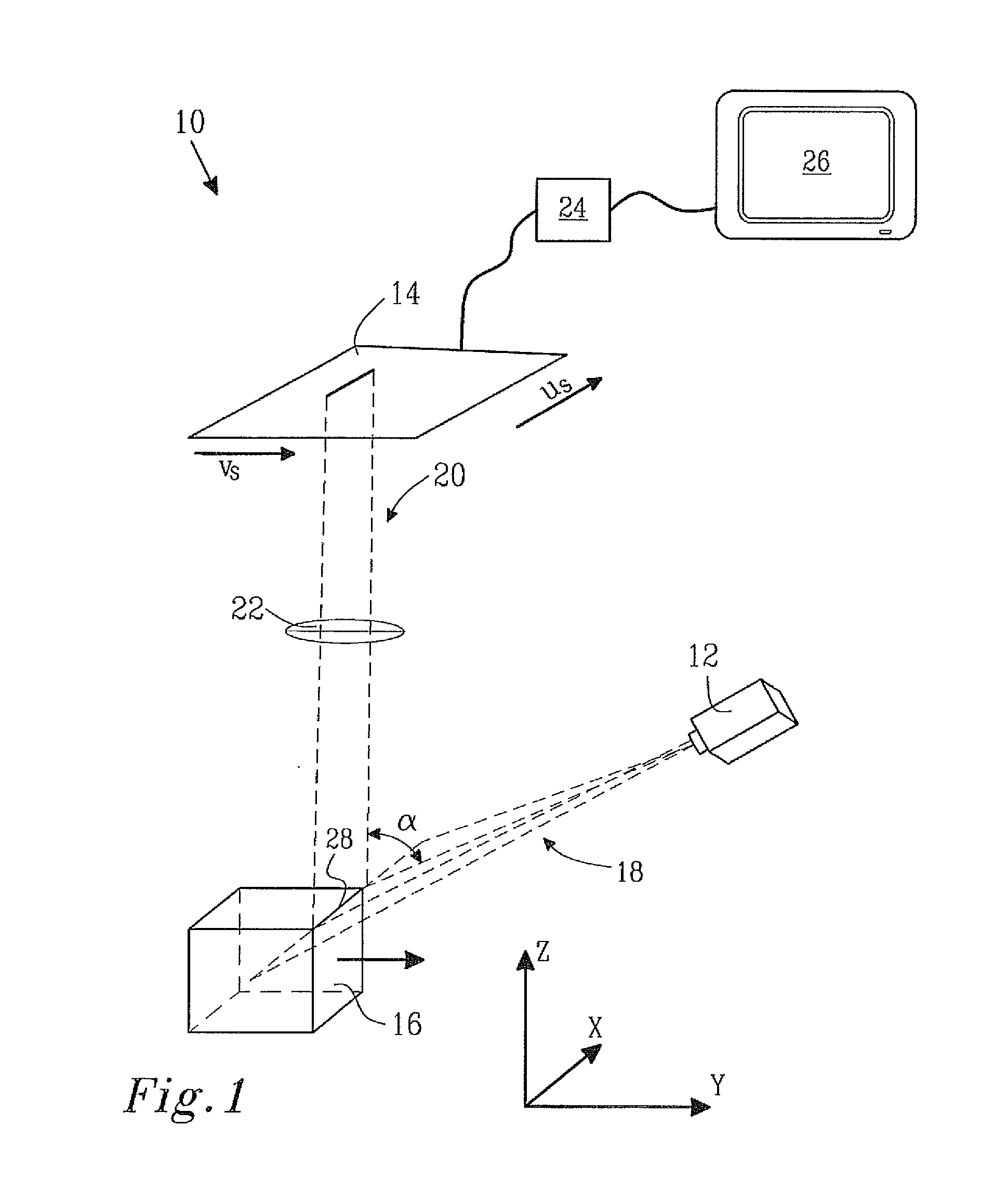
[0114]FIG. 7 further illustrates a preferred measuring system 10 for performing the estimation method according to the invention. The FIG. 7 measuring system 10 comprises two light sources, the first light source 12 and a second light source 46. The first light source 12 is adapted to generate a region with substantially homogenous light to be used in the apparent movement method as discussed above, whereas a second light source 46 may preferably be adapted to generate light well suited for generating three-dimensional images of objects. Furthermore, the sensor 14 of the measuring system 10 of FIG. 7 may be adapted to generate two sub-images 44′, 44″ for each one of least two subsequent time instants and may thus be used for generating two sets SI1, SI2 of sub-images. The first set of sub-images SI1 may be used for generating images for determining characteristics of a measure object, in particular the three-dimensional contour of the same. The second set of sub-images SI2 may be us...


PUM


Abstract

The present invention relates to a method for determining the extension of a trajectory in a space-time volume of measure images. The space-time volume of measure images is generated by a measuring method utilizing a measuring system comprising a first light source and a sensor. The measuring method comprises a step of, in a predetermined operating condition of the measuring system, moving a measure object along a first direction of movement in relation to the measuring system while the first light source illuminates the measure object whereby the sensor generates a measure image of the measure object at each time instant in a set of at least two subsequent time instants, thus generating said space-time volume of measure images wherein a feature point of the measure object maps to a trajectory in the space-time volume.

Description

TECHNICAL FIELD[0001]The present invention relates to a method for determining the extension of a trajectory in a space-time volume of measure images. The space-time volume of measure images is generated by a measuring method utilizing a measuring system comprising a first light source and a sensor. The measuring method comprises a step of, in a predetermined operating condition of the measuring system, moving a measure object along a first direction of movement in relation to the measuring system while the first light source illuminates the measure object whereby the sensor generates a measure image of the measure object at each time instant in a set of at least two subsequent time instants, thus generating the space-time volume of measure images wherein a feature point of the measure object maps to a trajectory in the space-time volume.[0002]The present invention further relates to a method for determining characteristics of a measure object by means of a measuring system comprisi...

Claims


Application Information

Patent Timeline
IPC IPC(8): G06K9/00
CPCG01B11/2522G01S7/481G01S17/89G01S17/48G01S17/50G01S17/42
Inventor JOHANNESSON, MATTIASTURBELL, HENRIKBENDERIUS, BJORN
Owner SICK IVP
Why Eureka
Try Eureka