Internal combustion engine controller

a technology for internal combustion engines and controllers, which is applied in the direction of electrical control, process and machine control, instruments, etc., can solve the problems of increasing exhaust emissions, reducing the performance of the above-mentioned fuel property sensor, and affecting the performance so as to achieve effective operation control, avoid excessive increase of the temperature of the catalyst bed, and maintain the effect of the catalyst converter 159

Inactive Publication Date: 2010-12-09
TOYOTA JIDOSHA KK
View PDF6 Cites 32 Cited by
  • Summary
  • Abstract
  • Description
  • Claims
  • Application Information

AI Technical Summary

Benefits of technology

[0114]In the present embodiment, when performance of refueling is detected, until learning of the fuel property is completed, the combustion conditions, such as the compression ratio and the ignition timing, are shifted toward the low alcohol concentration side; i.e., such that occurrence of anomalous combustion, such as knocking, is suppressed. With this operation, occurrence of anomalous combustion, such as knocking, in a period before completion of re-learning of the property of fuel is suppressed to a possible extent. Therefore, even when the property of fuel greatly changes due to, for example, refueling, the operation control of the engine 1 can be performed properly.
[0115]In the present embodiment, the above-described processing is not performed automatically when refueling is performed, but performed when a change in the property of fuel due to refueling is detected. That is, even when refueling is performed, the combustion control is performed under ordinary combustion conditions if the property of fuel does not change. With this operation, effective operation control can be performed for the engine 1.
[0116]In the present embodiment, when the combustion conditions are shifted upon detection of refueling and a change in the property of fuel such that the compression ratio is lowered and the ignition timing is delayed, the fuel-injection-quantity increase correction for protecting the catalyst converter 159 is performed so as to conform to the shift. With this operation, even when the above-described combustion condition shift is performed, excessive increase of the catalyst bed temperature is avoided, and the performance of the catalyst converter 159 can be maintained well.
[0117]FIG. 8 is a schematic diagram showing the overall configuration of a system S according to another embodiment which has a configuration modified from the configuration of the embodiment shown in FIG. 1. Notably, for the present embodiment, except for the following description, descriptions of the configuration, operation, action, and effects in the above-described first embodiment are incorporated herein by reference, so long as no technical inconsistencies are involved.
[0119]In the present embodiment, the fuel supply system 16 is configured to circulate fuel between the fuel tank 161 and the injector 162 (for example, a common-rail-type fuel injection system has such a configuration). Specifically, the fuel supply system 16 includes a return pipe 165. This return pipe 165 is configured to return to the fuel tank 161 the fuel F which was not injected from the injector 162.

Problems solved by technology

Presently, the above-mentioned fuel property sensor is, in general, not very high in accuracy, and may deteriorate with time.
Therefore, in the case of a conventional internal combustion engine of the above-mentioned type, when the property of fuel changes greatly due to refueling or the like, operation control suitable for the changed fuel property is not performed, which may cause troubles such as a drop in performance, and increase in exhaust emissions.
In such a case, if combustion conditions suitable for the fuel whose ethanol concentration is high (a high compression ratio, an advanced ignition timing, etc.) are maintained, anomalous combustion, such as knocking or pre-ignition, may occur.

Method used


Image

  • Internal combustion engine controller
  • Internal combustion engine controller
  • Internal combustion engine controller

Examples


Embodiment Construction

[0031]An embodiment of the present invention (the best mode contemplated by the applicant at the time of filing the present application) will next be described with reference to the drawings.

[0032]Notably, the following description of the embodiment merely describes a specific example of the present invention specifically to a possible extent so as to satisfy requirements regarding a specification (requirement regarding description and requirement regarding practicability) required under the law. Therefore, as described below, the present invention is not limited to the specific structure of the embodiment which will be described below. Various modifications of the present embodiment are described together at the end of the specification, because understanding of the consistent description of the embodiment is hindered if such modifications are inserted into the description of the embodiment.

[0033]

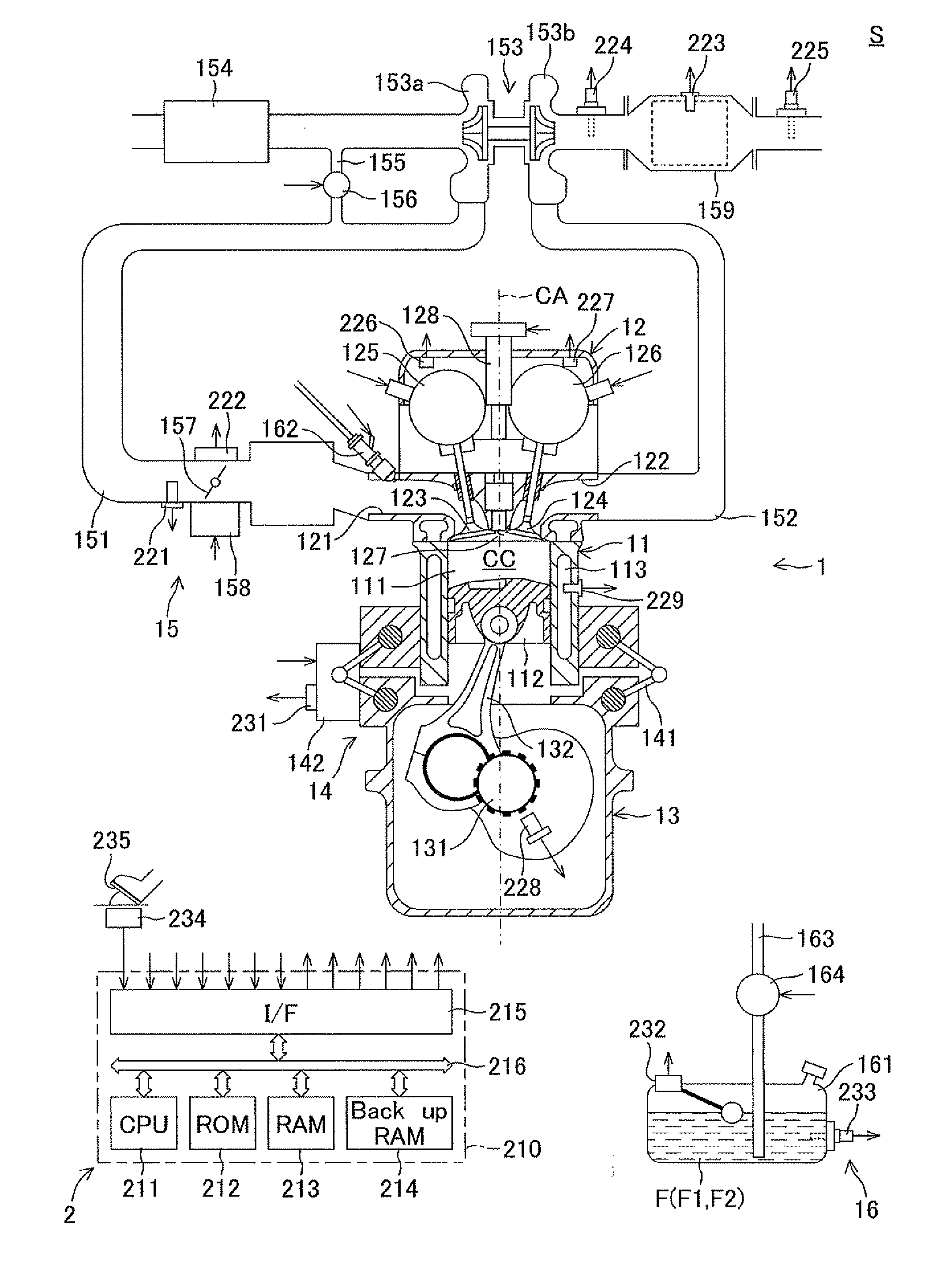
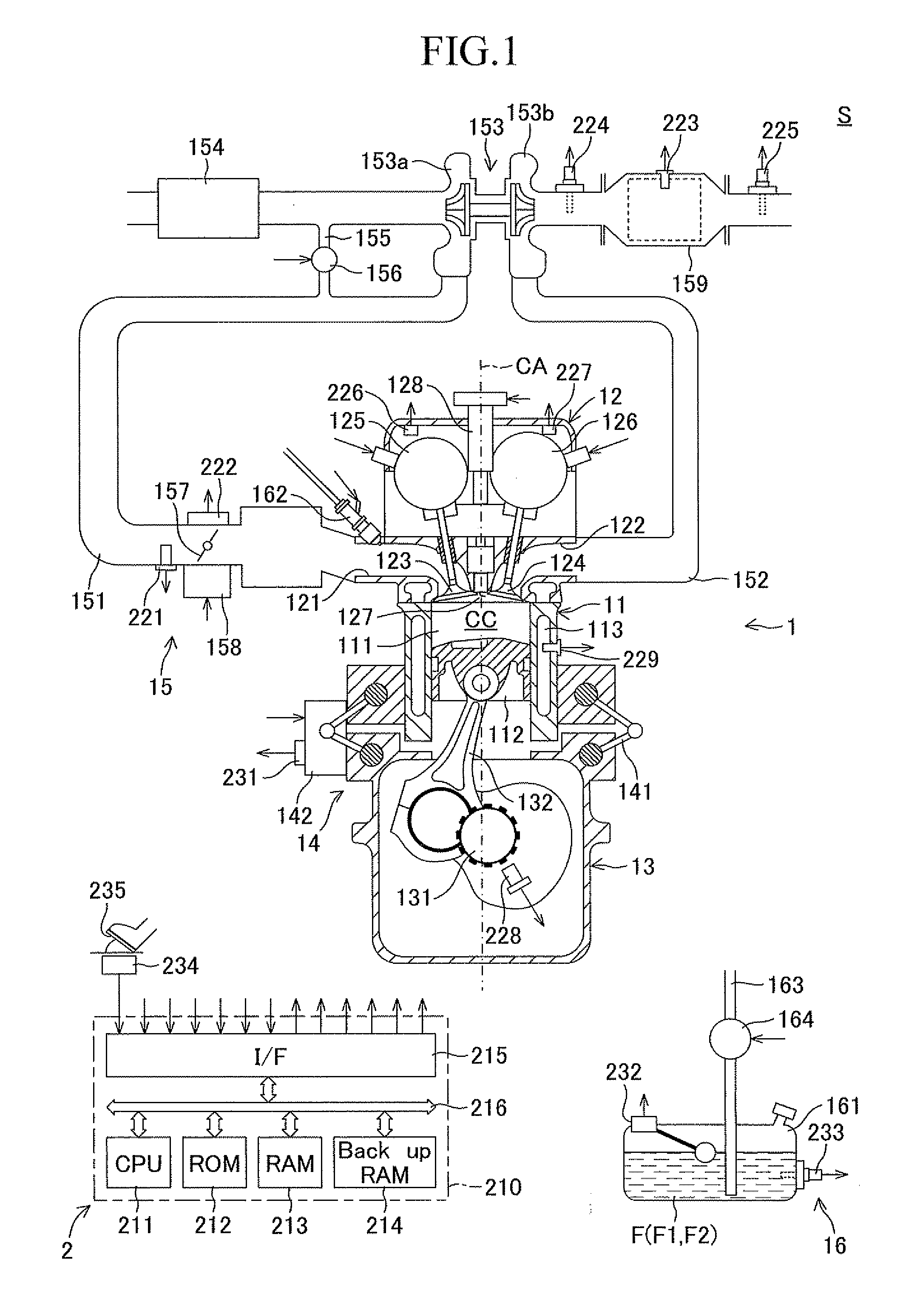
[0034]FIG. 1 is a schematic diagram showing the overall configuration of a system S (a...


PUM


Abstract

A controller (2) of the present invention includes a learning section which learns the property of fuel; a control section which controls combustion conditions (compression ratio, ignition timing, etc.) within a combustion chamber (CC) on the basis of the leaned property; and a supply-source-status detection section which detects a change in the statue of a fuel supply source (161) for supplying the fuel to a fuel injector (162). When a change in the status of the fuel supply source (161) is detected, before re-learning of the fuel property, the control section (2) shifts the combustion conditions based on the learned fuel property such that occurrence of anomalous combustion is suppressed.

Description

TECHNICAL FIELD[0001]The present invention relates to an apparatus for controlling operation of an internal combustion engine (hereinafter referred to as an “internal combustion engine controller”).BACKGROUND ART[0002]There have been proposed various internal combustion engines which can use a plurality of types of fuel. In particular, in recent years, active attempts have been made toward use of alternate fuel (use of bio-ethanol for gasoline engines and use of bio-diesel fuel for diesel engines). The mixing ratio of bio-fuel to gasoline or light oil varies greatly. For example, in the case of ethanol-containing gasoline fuel, its ethanol concentration varies greatly from “E3” (gasoline fuel whose ethanol content is x % is generally called Ex; this also applies to the following description) to “E85” and then to “E100,” whose ethanol content is 100%.[0003]A known internal combustion engine of such a type includes a fuel property sensor (an alcohol concentration sensor, etc.) for det...

Claims


Application Information

Patent Timeline
Patent Type & Authority Applications(United States)
IPC IPC(8): F02D41/30
CPCF02D15/02F02D19/0628F02D41/0025F02D41/22F02D41/2441F02D41/2451F02P5/1527Y02T10/36F02D19/088F02D19/0665F02D19/084F02D19/087F02D2200/0612Y02T10/30Y02T10/40
Inventor UTSUMI, SHINTARO
Owner TOYOTA JIDOSHA KK
Why Eureka
Try Eureka