Support structure for cooling unit for vehicle

Inactive Publication Date: 2010-12-16
TOYODA IRON WORKS CO LTD
View PDF8 Cites 17 Cited by
  • Summary
  • Abstract
  • Description
  • Claims
  • Application Information

AI Technical Summary

Benefits of technology

[0007]The invention has been made under such circumstances, and an object of the invention is to make it possible to smoothly move a cooling unit toward

Problems solved by technology

In addition, fragile portions are provided in the elongate holes, and the fragile portions are broken when the external force equal to or larger than a predetermined value is applied.
However, in the conventional support structures, because both of the first support point and the second support point are moved toward the rear side of

Method used


Image

  • Support structure for cooling unit for vehicle
  • Support structure for cooling unit for vehicle
  • Support structure for cooling unit for vehicle

Examples


Example

First Embodiment

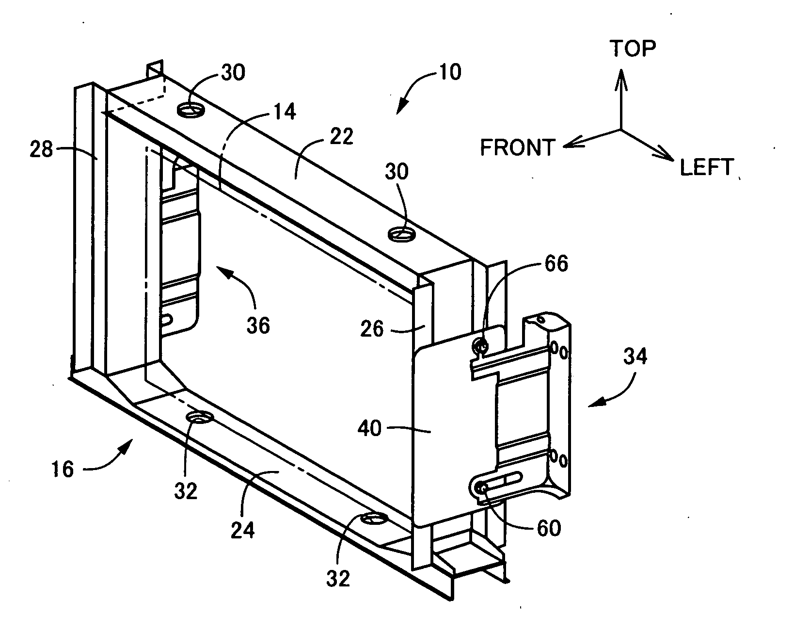
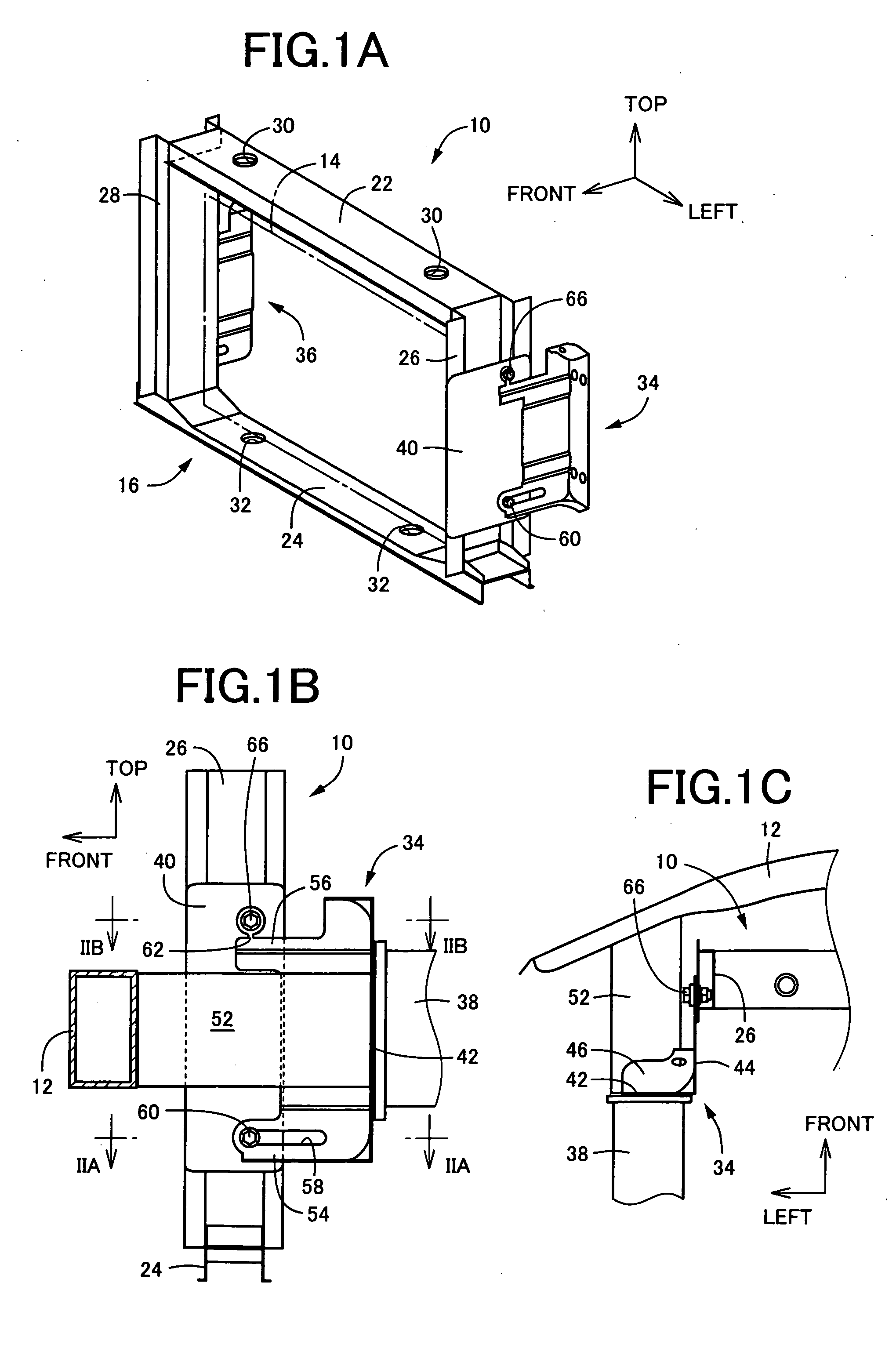
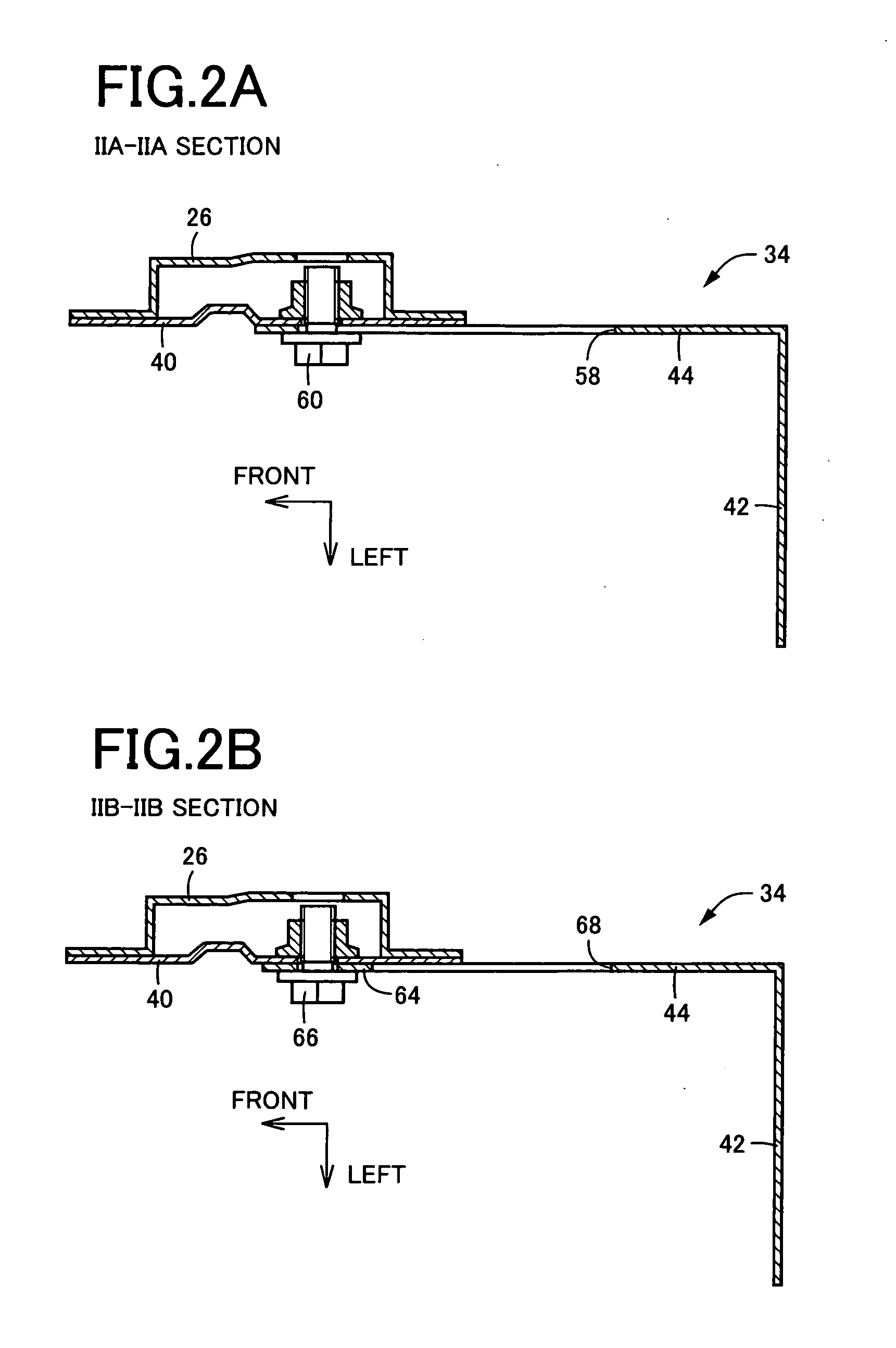
[0039]Hereinafter, a first embodiment of the invention will be described in detail with reference to the drawings. FIGS. 1A to 1C are diagrams showing a support structure for a cooling unit for a vehicle according to the first embodiment of the invention. FIG. 1A is a schematic perspective view, FIG. 1B is a side view showing the support structure at a left side of a vehicle, which is seen from the left side of the vehicle, and FIG. 1C is a plan view showing the support structure at the left side of the vehicle, which is seen from a top of the vehicle. A cooling unit 10 in the first embodiment is a radiator that cools a cooling fluid for cooling an engine. The cooling unit 10 includes a rectangular radiator body 14, and a radiator support 16 in the form of a frame, which supports the radiator body 14. The cooling unit 10 is disposed in substantially parallel with the width direction of the vehicle at a position behind a bumper reinforcement 12 disposed at the front s...

Example

Second Embodiment

[0054]Next, a second embodiment of the invention will be described. In the second embodiment, portions, which are substantially the same as those in the first embodiment, will be denoted by the same reference numerals, and detailed description thereof will be omitted.

[0055]FIG. 6 is a diagram, which is a side view corresponding to FIG. 1B, for showing a support structure using a support bracket 70 on the left side. FIGS. 7A and 7B are sectional views showing an enlarged section VIIA-VIIA and an enlarged section VIIB-VIIB in FIG. 6, respectively. FIG. 8 is a perspective view showing only the support bracket 70. The support bracket 70 is integrally provided with the fixation plate portion 42, the support plate portion 44, and the connection plate portions 46 and 48, as well as the support bracket 34. The fixation plate portion 42 is fixed integrally to the front end surface of the front side member 38, and the support plate portion 44 supports the side radiator suppor...

Example

Third Embodiment

[0063]FIGS. 11 to 14 show a support bracket 90 in a third embodiment. When the support bracket 90 in the third embodiment is compared with the support bracket 70 in the second embodiment, the support bracket 90 is different from the support bracket 70 in that an elongate hole 92 is formed in the first retention portion 72 to linearly extend substantially horizontally in the front-rear direction of the vehicle, and the first fastening bolt 78 can be moved toward the rear side of the vehicle along the elongate hole 92. FIG. 11 is a side view corresponding to FIG. 6. FIGS. 12A and 12B are sectional views showing an enlarged XIIA-XIIA section and an enlarged XIIB-XIIB section in FIG. 11, respectively. FIG. 13 is a perspective view showing only the support bracket 90. FIG. 14 is a side view showing a state in which the cooling unit 10 has been displaced toward the rear side of the vehicle.

[0064]The position of the elongate hole 92 is set so that the first fastening bolt 7...


PUM


Abstract

It is provided a support structure for a cooling unit for a vehicle, in which in one straight side edge portion of a rectangular cooling unit, a first support point and a second support point, which are set to be away from each other in a longitudinal direction of the one side edge portion, are supported by a first retention portion and a second retention portion, respectively, the first retention portion and the second retention portion being provided in a single support bracket fixed integrally to a vehicle body, the second retention portion supporting the second support point through a fragile portion that is broken to permit the second support point to be separated from the second retention portion when an external force equal to or larger than a predetermined value is applied to the second support point in a direction toward a rear side of a vehicle; and when the fragile portion is broken, the second support point being permitted to move toward the rear side of the vehicle, and to pivot in a direction of an arc with a center at the first support point.

Description

INCORPORATION BY REFERENCE[0001]The disclosure of Japanese Patent Application No. 2009-139671 filed on Jun. 10, 2009 including the specification, drawings and abstract is incorporated herein by reference in its entirety.BACKGROUND OF THE INVENTION[0002]1. Field of the Invention[0003]The invention relates to a support structure for a cooling unit for a vehicle, and in particular to improvement of a support structure in which one straight side edge portion of a rectangular cooling unit is supported at two points that are away from each other in a longitudinal direction, and the cooling unit is permitted to be displaced toward a rear side of a vehicle when a predetermined external force is applied in a direction toward the rear side of the vehicle.[0004]2. Description of the Related Art[0005]There is known a support structure for a cooling unit for a vehicle, in which in one straight side edge portion of a rectangular cooling unit, a first support point and a second support point, whic...

Claims


Application Information

Patent Timeline
IPC IPC(8): B60R11/00
CPCB60K11/04B60R19/34B60R2021/343
Inventor YOKOI, KAZUHIKOKOSAKA, HIROYASU
Owner TOYODA IRON WORKS CO LTD
Why Eureka
Try Eureka