System, method, and apparatus for magnetic resonance rf-field measurement

a magnetic resonance imaging and rf field technology, applied in the field of medical imaging systems, can solve the problems of limiting the clinical application of such techniques at a high magnetic field, long repetition time, inaccurate other techniques over certain ranges, etc., and achieve the effect of efficient determination of b1

Active Publication Date: 2010-12-16
GENERAL ELECTRIC CO
View PDF9 Cites 28 Cited by
  • Summary
  • Abstract
  • Description
  • Claims
  • Application Information

AI Technical Summary

Benefits of technology

[0008]It would therefore be desirable to have a system and apparatus that efficiently determines a B1 or RF field of a magnetic resonance system without some or all the aforementioned drawbacks.

Problems solved by technology

Still other techniques are inaccurate over certain ranges of B1 field, and / or are dependent on large RF power depositions.
Although such a technique is more accurate than others over a larger range of flip angles, such a technique is B0 dependent and often relies on a relatively long repetition time (TR) requirement.
However, the specific absorption rate (SAR) associated with such techniques can limit the clinical application of such techniques at a high magnetic field.

Method used


Image

  • System, method, and apparatus for magnetic resonance rf-field measurement
  • System, method, and apparatus for magnetic resonance rf-field measurement
  • System, method, and apparatus for magnetic resonance rf-field measurement

Examples


Embodiment Construction

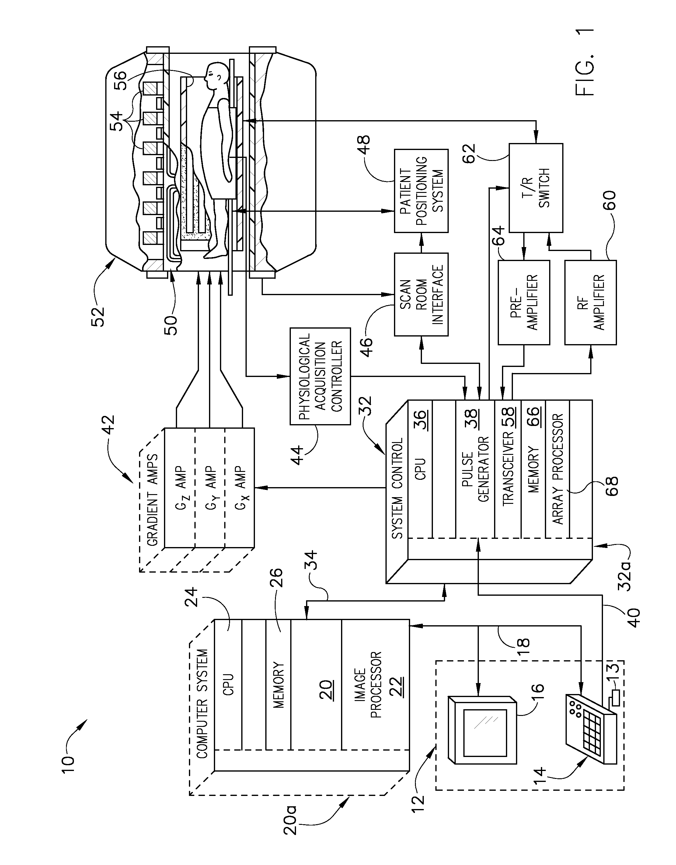
[0021]Referring to FIG. 1, the major components of an exemplary magnetic resonance imaging (MRI) system 10 incorporating embodiments of the present invention are shown. The operation of the system is controlled from an operator console 12 which includes a keyboard or other input device 13, a control panel 14, and a display screen 16. The console 12 communicates through a link 18 with a separate computer system 20 that enables an operator to control the production and display of images on the display screen 16. The computer system 20 includes a number of modules which communicate with each other through a backplane 20a. These include an image processor module 22, a CPU module 24 and a memory module 26 that may include a frame buffer for storing image data arrays. The computer system 20 is linked to archival media devices, permanent or back-up memory storage or a network for storage of image data and programs, and communicates with a separate system control 32 through a high speed ser...


PUM


Abstract

An apparatus, system, and method including a magnetic resonance imaging (MRI) apparatus includes a magnetic resonance imaging (MRI) system having a plurality of gradient coils positioned about a bore of a magnet, and an RF transceiver system and an RF switch controlled by a pulse module to transmit RF signals to an RF coil assembly to acquire MR images, and a computer. The computer is programmed to apply a first off-resonant radio frequency (RF) pulse at a first frequency different than the resonant frequency to a plurality of nuclei excited at a resonant frequency, acquire a first signal from the plurality of nuclei after application of the first off-resonant RF pulse, determine a phase shift from the first signal based on the first off-resonant RF pulse, determine a B1 field based on the phase shift, and store the B1 field on a computer readable storage medium.

Description

GOVERNMENT RIGHTS IN THE INVENTION[0001]The U.S. Government has a paid-up license in this invention and the right in limited circumstances to require the patent owner to license others on reasonable terms as provided for by the terms of Government grant number 5R01EB005307-02 awarded by the National Institute of Health.BACKGROUND OF THE INVENTION[0002]The present invention relates generally to medical imaging systems and, more particularly, to determination of B1 fields associated with magnetic resonance imaging.[0003]When a substance such as human tissue is subjected to a uniform magnetic field (polarizing field B0), the individual magnetic moments of the spins in the tissue attempt to align with this polarizing field, but precess about it in random order at their characteristic Larmor frequency. If the substance, or tissue, is subjected to a magnetic field (excitation field B1) which is in the x-y plane and which is near the Larmor frequency, the net aligned moment, or “longitudin...

Claims


Application Information

Patent Timeline
Patent Type & Authority Applications(United States)
IPC IPC(8): G01R33/44
CPCA61B5/0402A61B5/055G01R33/246G01R33/583A61B5/318
Inventor SACOLICK, LAURA I.VOGEL, MIKA W.WIESINGER, FLORIANHANCU, ILEANA
Owner GENERAL ELECTRIC CO
Why Eureka
Try Eureka