Display apparatus

a technology of display apparatus and buffer, which is applied in the direction of television system, static indicating device, instruments, etc., can solve the problems of huge power consumption at the driving circuit of optical sensors and at the buffer, and achieve the effect of suppressing power consumption

Inactive Publication Date: 2010-12-16
SHARP KK
View PDF16 Cites 29 Cited by
  • Summary
  • Abstract
  • Description
  • Claims
  • Application Information

AI Technical Summary

Benefits of technology

[0006]With the foregoing in mind, it is an object of the present invention to provide a display apparatus with image capturing function including optical sensors in its pixels, and particularly a display apparatus capable of capturing an image while suppressing the power consumption.
[0008]According to the above configuration, by suppressing an output to the subsequent stage of the sensor column amplifier or the buffer amplifier in accordance with a standby signal, the power consumption at these amplifiers can be suppressed.
[0012]As described above, according to the present invention, it is possible to provided a display apparatus with image capturing function including optical sensors its pixels, particularly a display apparatus capable of capturing an image while suppressing the power consumption.

Problems solved by technology

In the conventional display apparatus with image capturing function, since signal charges outputted from all of the optical sensors are processed by the driving circuit for the optical sensors and the buffer circuit, power consumption at the driving circuit for the optical sensors and at the buffer is huge.

Method used


Image

  • Display apparatus
  • Display apparatus
  • Display apparatus

Examples


embodiment 1

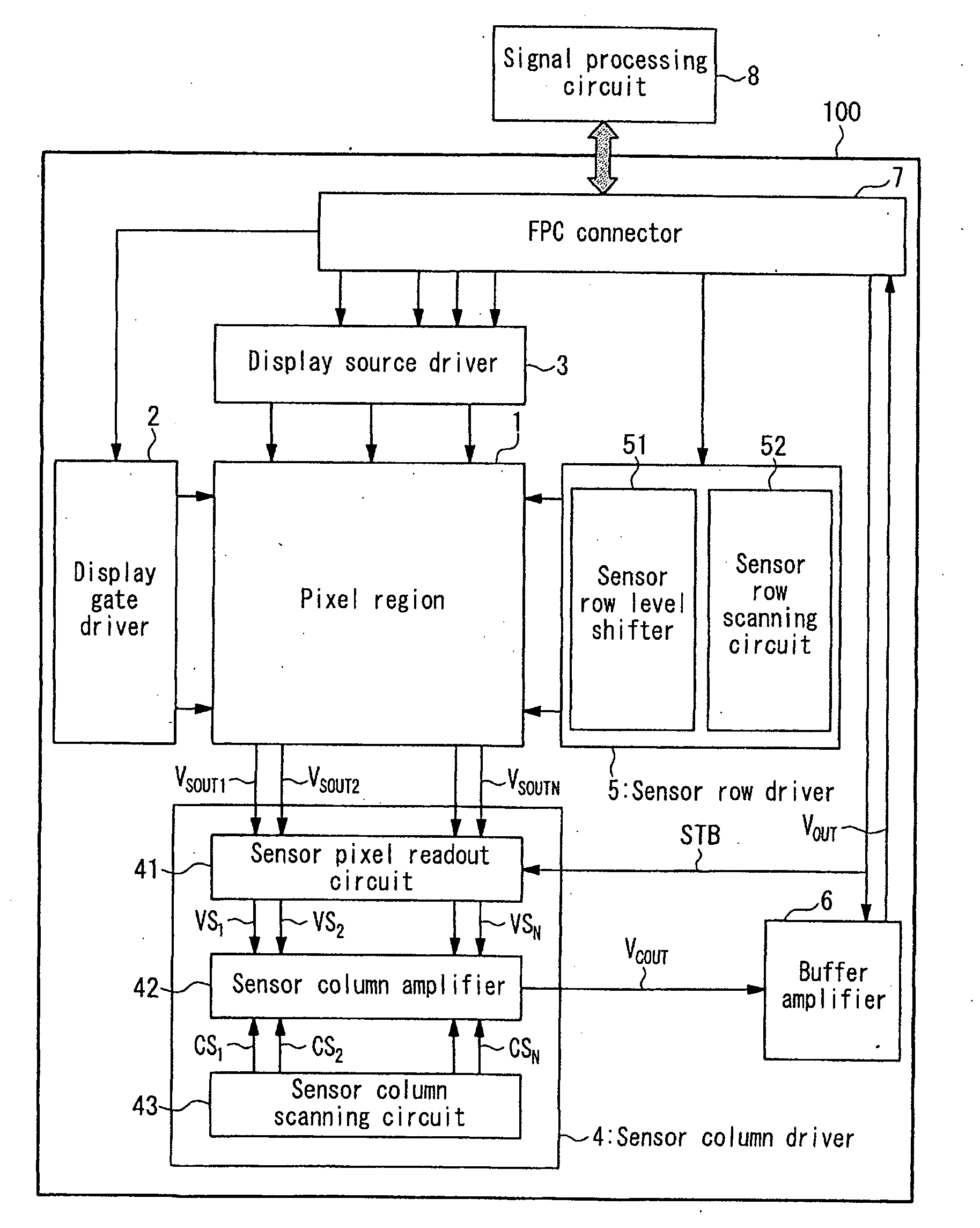
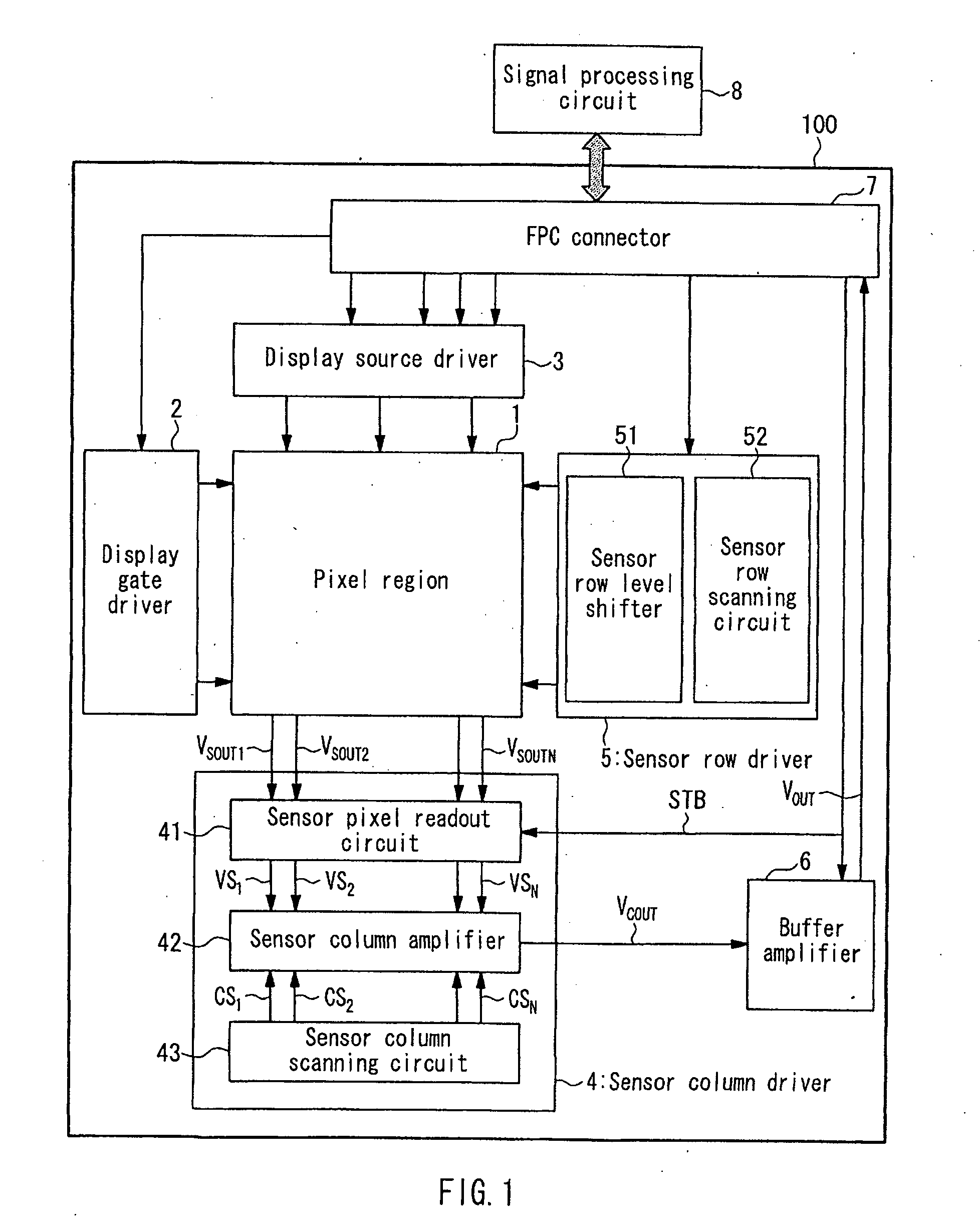
[0026]FIG. 1 is a block diagram showing a schematic configuration of an active matrix substrate 100 that a liquid crystal display apparatus according to one embodiment of the present invention includes. As shown in FIG. 1, the active matrix substrate 100 includes, on a glass substrate, at least a pixel region 1, a display gate driver 2, a display source driver 3, a sensor column driver 4, a sensor row driver 5, a buffer amplifier 6, and an FPC connector 7. Further, a signal processing circuit 8 for processing image signals captured by optical sensors (will be described below) in the pixel region 1 is connected to the active matrix substrate 100 via the FPC connector 7 and an FPC (not shown).

[0027]It should be noted that the components provided on the active matrix substrate 100 can be also formed monolithically on the glass substrate using a semiconductor process. Or, the drivers among the components may be mounted on the glass substrate using a chip on glass (COG) technique or the ...

embodiment 2

[0044]Embodiment 1 referred to the configuration in which the standby switching circuit is provided in the sensor column amplifier 42. In contrast, a display apparatus according to Embodiment 2 includes a sensor column amplifier 42a instead of the sensor column amplifier 42, and a buffer amplifier 6a including a standby switching circuit instead of the buffer amplifier 6 as shown in FIG. 10. It should be noted that, as shown in FIG. 11, the sensor column amplifier 42a is different from the sensor column amplifier 42 in Embodiment 1 in that it does not include a standby switching circuit.

[0045]As shown in FIG. 10, the buffer amplifier 6 is provided with a standby switching circuit for performing switching so that a constant voltage VSSA is supplied to bias transistors M11 and M9 when the level of the standby signal STB is high (standby ON) and a reference bias voltage VB2 is supplied to the bias transistors M11 and M9 when the level of the standby signal STB is low (standby OFF).

[004...


PUM


Abstract

The present invention provides a display apparatus with image capturing function including optical sensors in its pixels, particularly a display apparatus capable of capturing an image while suppressing the power consumption. The display apparatus includes: optical sensors and sensor wirings provided in a pixel region of an active matrix substrate; a sensor row driver for selecting the optical sensors row by row; a sensor pixel readout circuit for reading out signal charges from the optical sensors in the selected row; a sensor column amplifier including the number of amplifiers corresponding to the rows of the optical sensors for generating a sensor output voltage; a sensor column scanning circuit for selecting the signal charges readout by the sensor pixel readout circuit column by column so that the selected signal charges being outputted to the sensor column amplifier; and a buffer amplifier (6) provided subsequent to the sensor column amplifier (24). The sensor column amplifier (42) or the buffer amplifier (6) is provided with a standby switching circuit for suppressing an output to a subsequent stage of either of the amplifiers in accordance with a standby signal.

Description

TECHNICAL FIELD[0001]The present invention relates to display apparatuses with image capturing function including optical sensors in their pixels, and particularly to display apparatuses capable of capturing an image while suppressing the power consumption.BACKGROUND ART[0002]Conventionally, there have been proposed display apparatuses with image capturing function capable of capturing an image of an object in the proximity of their displays by means of, for example, optical sensors, such as photodiodes, in the pixels. Such display apparatuses with image capturing function are intended to be used as display apparatuses for interactive communications and display apparatuses with touchscreen function.[0003]In a conventional display apparatus with image capturing function, when well-known components such as signal lines, scan lines, thin film transistors (TFTs), and pixel electrodes are formed on an active matrix substrate using a semiconductor process, photodiodes are formed in the pi...

Claims


Application Information

Patent Timeline
Patent Type & Authority Applications(United States)
IPC IPC(8): G09G5/00H04N5/335
CPCG02F2001/13312Y02D10/153G06F1/3218G06F1/3265G06F3/0412G06F3/042G09G3/3648G09G2310/0291G09G2330/021G09G2360/14H04N1/00127H04N1/00129H04N1/0461H04N1/195H04N5/335H04N2201/0081G06F1/32Y02D10/00G02F1/13312H04N25/00
Inventor KATOH, HIROMIBROWN, CHRISTOPHER
Owner SHARP KK
Why Eureka
Try Eureka