Direction-finding method and installation for detection and tracking of successive bearing angles

a direction-finding and tracking technology, applied in direction finders, instruments, measurement devices, etc., can solve the problems of ambient noise loss, decrease in the intensity of array signals, etc., and achieve the effect of less estimation errors, reduced trace quality, and varied confidence of bearing trace displays

Inactive Publication Date: 2010-12-16
ATLAS ELEKTRONIC GMBH
View PDF1 Cites 11 Cited by
  • Summary
  • Abstract
  • Description
  • Claims
  • Application Information

AI Technical Summary

Benefits of technology

[0011]One advantage of the invention is automated initialization, extraction, confirmation and deletion of bearing traces without any operator action. A further advantage of the direction-finding method according to the invention is that a probably curved profile of a bearing trace can also be approximated by linear subelements, because of the density of the measured bearing angles over time. This is true even when the bearing angle to a target which is moving on a constant course and at a constant velocity with respect to the direction-finding installation does not change by a constant bearing rate for a constant movement interval of the target. The structuring of the model variances and the strength of the process noise result in an approximation which takes account of this behavior of the bearing angle.
[0012]In one advantageous development of the direction-finding method according to the invention, the quality is investigated with which the measured bearing angle and possibly the measured intensity fits the estimated bearing trace and whether the most recently estimated bearing angle can be displayed as an extension of the previous bearing trace. Taking account of a preset density for new bearing traces in the azimuth panorama or in the azimuth sector, and a preset density of false alarms, a trace quality is determined for each bearing trace, together with the association probability. This trace quality is added over a predeterminable number of clock cycles, and takes account of the entire history of the bearing trace, or of a part of the history of the bearing trace. The respectively currently calculated trace quality is compared with two bounds in order to use the bearing angle to initiate or to confirm a new provisional bearing trace, and to confirm or to delete an existing bearing trace. If there is no measured value, the most recent estimate is continued by prediction, and the trace quality is decreased. Superfluous measurements, with which no bearing trace can be associated, are assessed as the start of a new bearing trace. The bounds are defined by predeterminable probabilities for the confirmation of a false bearing trace or the deletion of a true bearing trace. The most recently determined bearing traces and their assessments are managed in a bearing trace list, and are displayed corresponding to the trace quality. These confirmed bearing traces can be marked, for example by color, and can thus be associated with a target.
[0013]In one advantageous development of the direction-finding method according to the invention, the bearing angle and possibly the trace intensity are determined from the predicted bearing angle and possibly the predicted intensity plus the difference of the measured and predicted bearing angle and possibly measured and predicted intensity, taking account of the estimation error and measurement error. This results in the bearing angle fitting the estimated bearing trace better the less the measured bearing angle and possibly the measured intensity differ from the estimated bearing angle and the estimated intensity, respectively, and the less the estimation error is.
[0014]In order to predict the next predicted state vector, according to one advantageous development of the direction-finding method according to the invention, the bearing rate determined from the previously estimated bearing trace, and possibly intensity rate or gradient of the bearing trace with respect to its angle profile and possibly its intensity, for the most recently determined bearing angle and possibly the most recently determined trace intensity are multiplied by the time interval and are added.
[0015]According to a further advantageous development of the invention, the estimation error is determined as a function of the most recently determined trace error, the model variances and the variance in the rate of change of the bearing rate and possibly intensity rate, and the covariance between the bearing angle and possibly the intensity and its rates of change. The estimation error becomes greater the greater the model variances are predetermined to be, and the greater the extent to which the estimated gradient differs from the previously determined gradient. By increasing the model variances, it is possible to associate the estimated bearing trace even with widely scattered measured bearing angles, and the bearing trace is not immediately terminated in the event of “spurious measured values” when, for example, the signal-to-noise ratio of the intensity fluctuates to a major extent, and no significant array signal is any longer received, for example because of changes in the transmission behavior in the propagation path of the sound waves between the target and the direction-finding installation.
[0016]The advantage of one development of the direction-finding method according to the invention is that the confidence of the bearing trace display can be varied by the upper bound on the trace quality. If the probability for confirmation of a false bearing trace is intended to be decreased, the upper bound is raised, and the number of confirmed bearing traces is reduced. This makes it possible to suppress bearing traces which are produced by reception of sound waves via sidelobes of the directional characteristic. Bearing traces from positions astern of the watercraft to which the direction-finding installation is attached, caused by the sound incidence of a propulsion propeller, are likewise suppressed.

Problems solved by technology

If the target is moving away from the direction-finding installation, the intensity of the array signal decreases, until it is lost in the ambient noise.

Method used


Image

  • Direction-finding method and installation for detection and tracking of successive bearing angles
  • Direction-finding method and installation for detection and tracking of successive bearing angles
  • Direction-finding method and installation for detection and tracking of successive bearing angles

Examples


Embodiment Construction

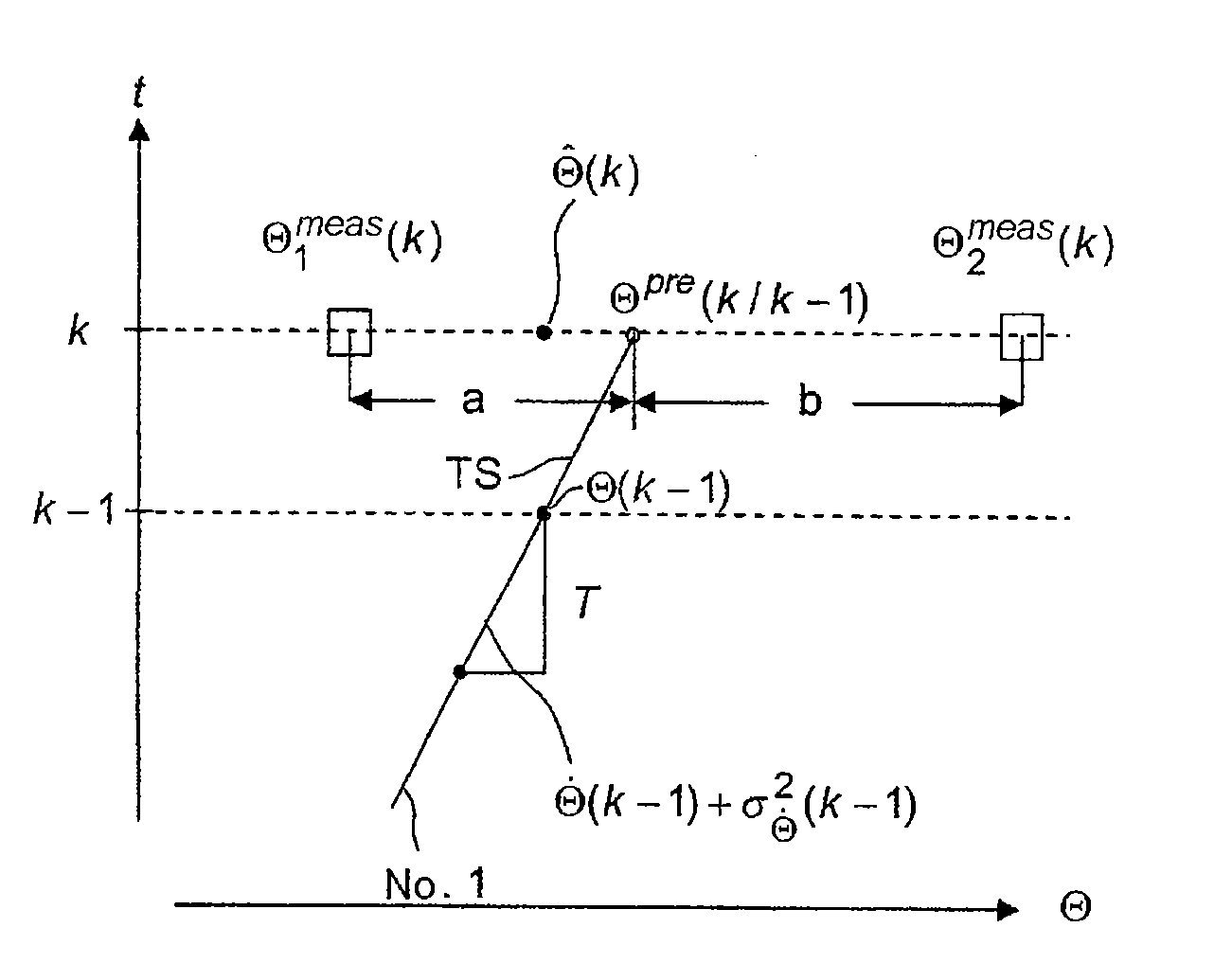
[0030]FIG. 1 shows a bearing / time diagram in which the bearing Θ, plotted along the horizontal axis, is shown against time, plotted along the vertical axis. This diagram shows a subelement TS of a bearing trace No. 1, which is estimated up to the time t=k−1 and is obtained by prediction of the bearing angle for the time t=k. For this purpose, starting from a bearing angle Θ(k−1) for the time t=k−1 on the bearing trace No. 1, a bearing angle Θpre(k / k−1) is predicted for the time t=k, based on historical measurement data up to the time t=k−1. The subelement TS has a linear profile over time. The bearing rate or gradient of the bearing trace {dot over (Θ)}(k−1) for the time t=k−1 is determined by regression analysis from the sequence of the associated measurements up to the time t=k−1, using a standard deviation σ{dot over (Θ)}(k−1). The two bearing angles Θ1meas(k) and Θ2meas(k) measured at t=k are tested using the predicted bearing angle Θ1pre(k / k−1) for association in pairs with the...


PUM


Abstract

A direction-finding method and apparatus for detection and tracking of successive bearing angles of sound-emitting targets, wherein intensity plots of successive clock cycles in a waterfall plot show bearing traces of successive bearing angles, and preferred bearing traces are marked by a tracker. In order to automate the setting and deletion of trackers, starting from trace state vectors, which are determined at the time t=k−1, are each associated with one bearing trace and each have a bearing angle as well as its time derivative, which is referred to as the bearing rate, and possibly an intensity and its time derivative, which is referred to as the intensity rate, and trace errors associated with the trace state vectors for the time t=k, predicted state vectors are predicted together with predicted estimation errors. Bearing traces are displayed as a function of a trace quality

Description

CROSS REFERENCE TO RELATED APPLICATION[0001]This application claims the priority of German patent application No. 10 2009 024 339.9-55, filed Jun. 9, 2009, the subject matter, in its entirety, is incorporated herein by reference.BACKGROUND OF THE INVENTION[0002]The invention relates to a direction-finding method for detection and tracking of successive bearing angles of targets which emit broadband sound, over the entire azimuth panorama or a predeterminable azimuth sector, using a direction-finding installation for receiving broadband sound waves according to the precharacterizing clause of Claim 1, and to a direction-finding installation according to the precharacterizing clause of Claim 14.[0003]In sonar technology, a passive direction-finding installation is used to monitor the entire azimuth or a sector, in order to detect noises from sound-emitting targets such as surface vessels, submarines, underwater vehicles or torpedoes, and to track bearing angles to the targets. The ter...

Claims


Application Information

Patent Timeline
Patent Type & Authority Applications(United States)
IPC IPC(8): G01S15/00
CPCG01S3/8006G01S3/8083
Inventor BRINKMANN, KEVINHURKA, JORGDAUN, MARTINAKOCH, WOLFGANGRUTHOTTO, EICKE
Owner ATLAS ELEKTRONIC GMBH
Why Eureka
Try Eureka