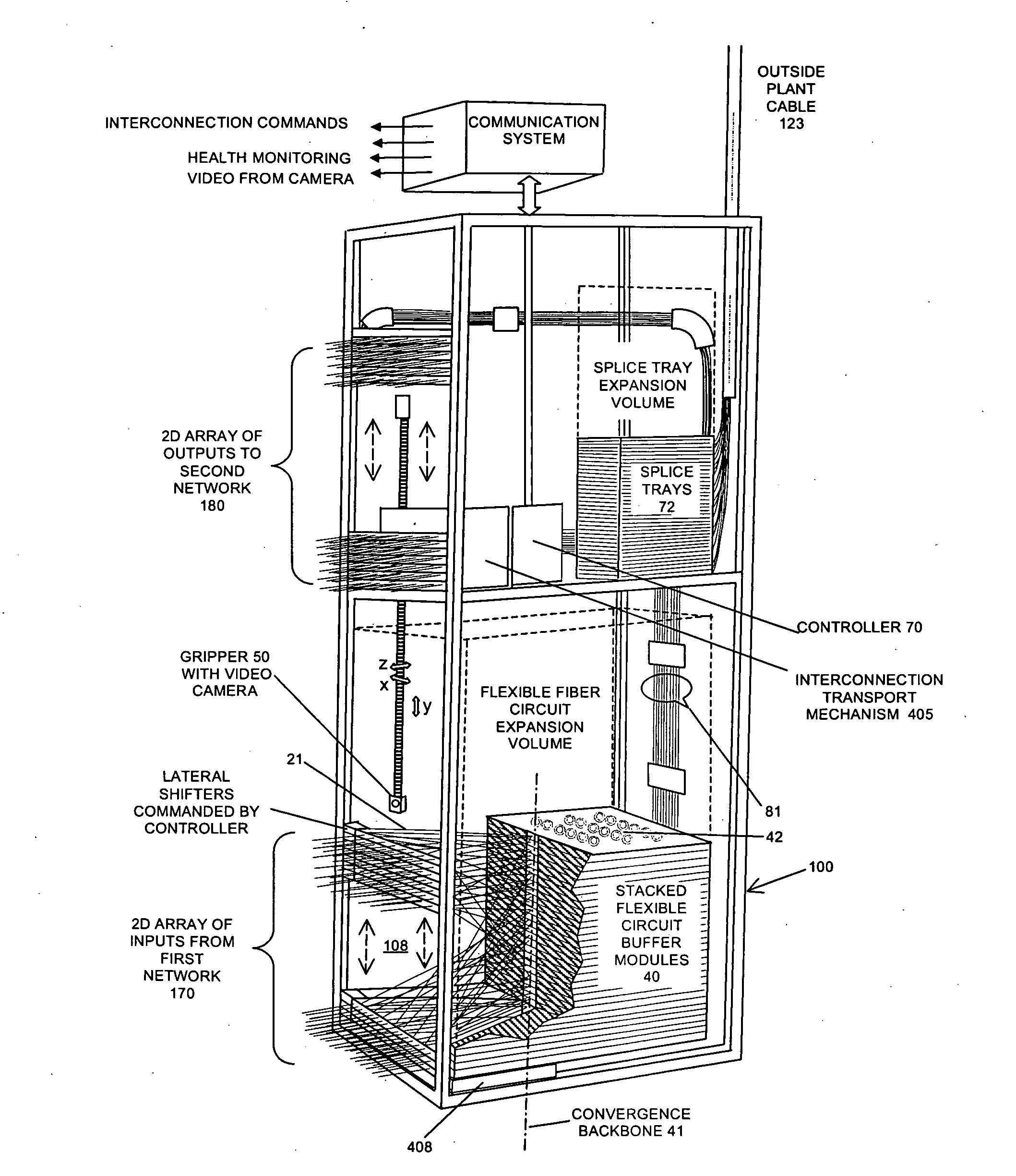
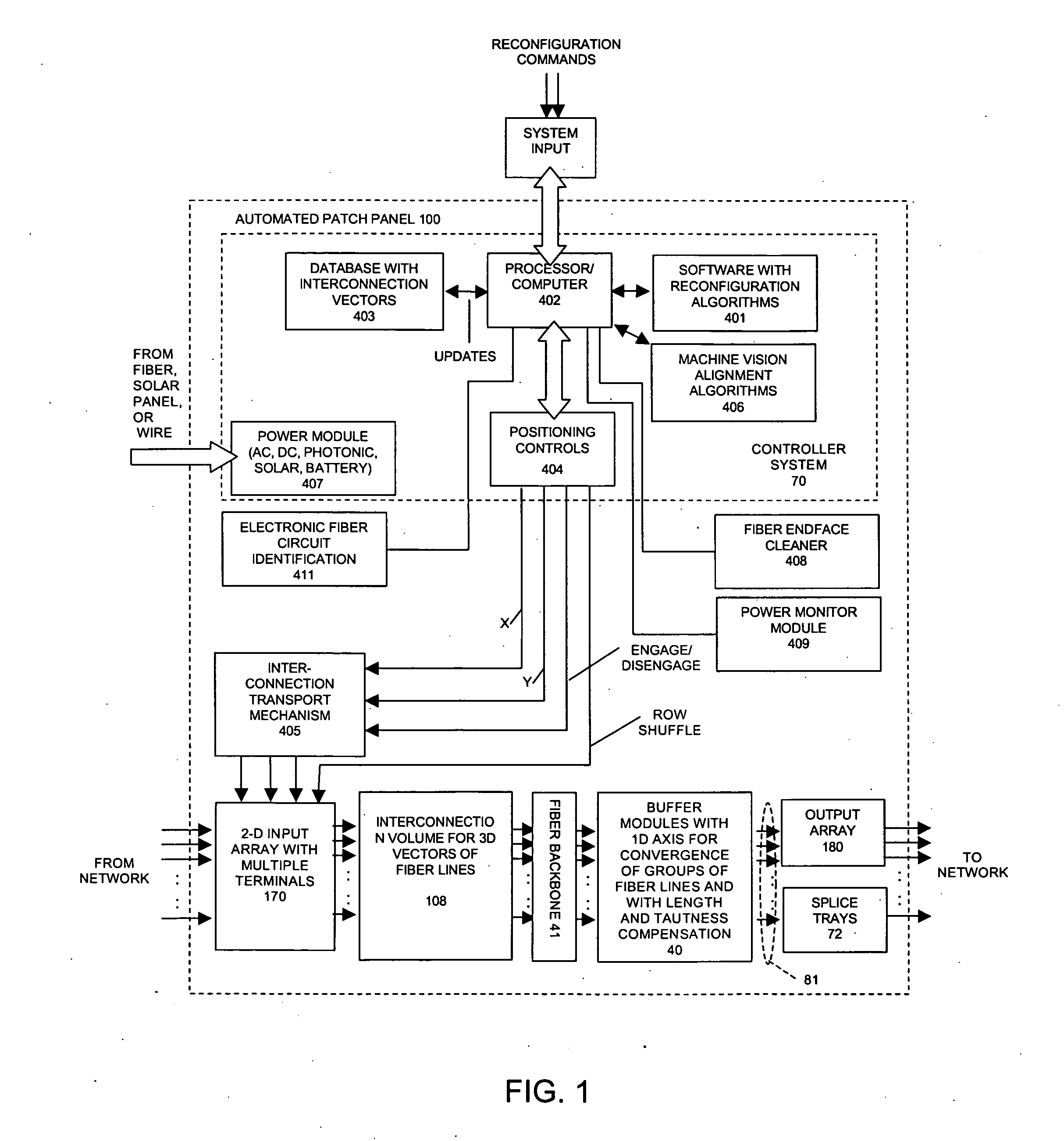
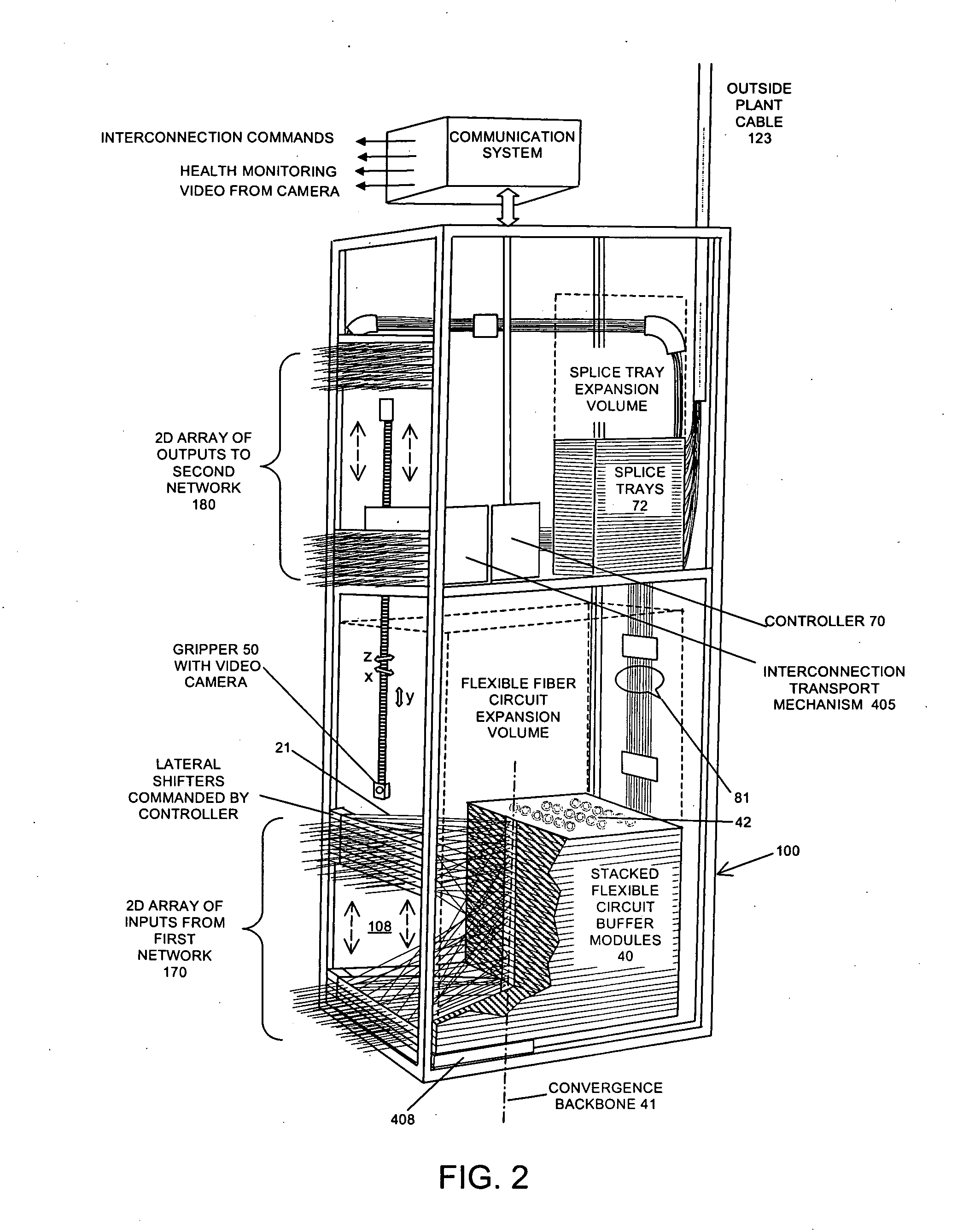
[0017]To meet these and other objectives we disclose in this application an automated, remotely controllable, optical cross-connect switch system that exhibits near zero insertion loss, high reliability and compact size. Further, the physical dimensions of these systems scale linearly, not geometrically (as n rather than n2) so they can readily be expanded to have capacity for thousands of fiber optic circuits. These features and advantages derive from a combination of unique dynamic elements and array geometries, and also from employment of non-blocking switch algorithms. They enable the unique optical cross-connect switch geometries to interconnect different optical networks in an automatic, remotely accessible fashion.
[0018]In a general example of a system in accordance with the invention, programmable and robotically changeable interconnections of large numbers (hundreds to thousands) of optical fibers, or in general any type of flexible transmission line, are achieved by employing a two-dimensional input array of connector terminals coupled externally to a first network. Latching optical connections can utilize long-wearing but replaceable connector-terminal interfaces that maintain the highest level of optical performance and modularity. Internally the terminals are joined by multiple interconnections within an intervening volume to a one-dimensional second array spaced apart from the first. Optical fiber lines from the second array are coupled through buffer modules, to a second network. The multiple lines between the two arrays are mapped to follow multiple interconnecting vectors in an ordered and rule-based fashion. Within the interconnection volume, the fibers are maintained in substantially straight lines by modular variable length buffers subsequent to the second array, each buffer confining a number of optical fiber lines and maintaining an adequate bend radius on the fibers but with capacity to retain excess fiber lengths. The buffers are scalable simply by incremental addition (typically stacking) and the output lines from the buffers can be connected through splice tray modules, again stackable so that more lines can be added. The arrays can also be arranged to divide the switch volume into multiple independent, non-interfering zones, which retain their independence for arbitrary and unlimited numbers of reconfigurations. The geometries of the terminals in the input array provide clearance for one or more robotic actuators to move within the interconnection volume substantially adjacent to the two-dimensional input array, and to be commanded by external signals to mechanically reconfigure the positions of connectors.
[0019]To reconfigure these interconnections at the first array, a non-interfering switch algorithm is disclosed, the algorithm based in part on knowledge of the existing line vectors of the optical lines between the input array and the intermediate array. The algorithm can employ either or both measurement of existing vector configurations or (more usually) stored data providing a data map of the existing connection paths. From such stored data the system controller generates a deterministic path dependent on and calculated from the changeable mapping of the vectorial patterns. In a particular example of a system, in accordance with the invention, motion along the path between a source address and a target address for a selected optical line is achieved both by following vertical columnar spaces within the input array, and laterally translating in the row direction in a manner to avoid entanglement with existing lines. In conjunction, docking ports or terminals are provided in the input array in positions which enable temporary storage or shifting of elements so as to preclude entanglement.
[0020]The system includes an electronic processor having access to a database of the existing interconnection vectors, and a software program for providing commands for the positioner to follow a deterministic path through the vectors of the lines in the interconnection volume. Upon receiving a signal command for the transfer of a connector from a chosen terminal to a target terminal, the processor conducts a sequence of coordinated motions relative to the input array to move the connector, and its attached optical fiber line, along the two-dimensional path of columns and rows, ultimately terminating at the target terminal. The compliance of the buffer element associated with the line being transferred enables variations in line length to be automatically compensated, without introduction of undue slackness, tensioning or bending of the optical fibers.
[0022]In a particular example in accordance with the invention, an automatic fiber optic patch-panel system comprises a two-dimensional input array of reconfigurable ports in a first plane, adjacent the interconnection volume through which optical fibers from the input array are mapped to a substantially linear array of optical lines converging along a backbone axis in a second plane spaced apart from the first plane. The backbone is defined by a plurality of low friction guides which converge the optical fibers into separate paths into an adjacent buffer module, for each set of optical lines, and the buffer module maintains the substantially straight path needed in the interconnection volume and controlled tension without excessive bending. The optical fibers exiting the buffers can be spliced to an optical fiber cable or terminate in an output connector array. In one example, all buffer modules comprise low-height containers, each including a number of circular chambers for receiving individual optical lines together with suitable stiffening elements. In another example, the buffer may comprise a row-height container with a sufficient internal capacity for receiving a length of optical fiber secured at spaced apart points in a manner which allows for a pre-determined length of fiber to be extracted and returned under tension control.
[0024]Low loss fiber optic connections to the input plane array of connector terminals are achieved by use of physical contact connectors inserted into precision alignment sleeves. With replaceable, sacrificial stub elements incorporated into the alignment sleeves at the front panel, the design enables the extension of service life. Since near zero overall insertion loss is desirable, the present application discloses the use of flexible fiber optic circuit structures with integral rigid spring elements that oppose excessive bending. Such structures are further designed to simultaneously maintain tension along the circuit and retain slack fiber length within separate cavities.