Linear compressor

a compressor and linear technology, applied in the direction of piston pumps, positive displacement liquid engines, pump components, etc., can solve the problems of difficult assembly with a component, low mass, and large mechanical loss of such motion conversion, so as to reduce the overall cost of manufacturing, prevent material waste, and achieve mass sufficient

Active Publication Date: 2010-12-16
LG ELECTRONICS INC
View PDF17 Cites 27 Cited by
  • Summary
  • Abstract
  • Description
  • Claims
  • Application Information

AI Technical Summary

Benefits of technology

[0037]In the linear compressor in accordance with the present invention, a piston, a muffler assembly, a supporter and a mass member are bolt joined to each other to configure a movable member, in which the mass member takes the form of a polygonal shape with plural ends to maintain an air-gap towards its neighboring components, such that an overall cost of manufacturing can be reduced by preventing a waste of materials for producing the mass member, and that the mass member has a sufficient mass considering the amount of materials used to reduce installation space. Furthermore, the mass member is safe not only from interference of its counterpart during the assembly, but also from interference of other neighboring components during the operation, thereby securing the operating reliability.
[0038]In addition, since all the components like a piston, a connecting member provided with permanent magnet, a supporter, a suction muffler and a mass member that constitute a movable member have their own guide holes or guide grooves, they are more likely to stay at accurate joining positions with guide pins being inserted into those guide holes or guide grooves during the assembly process of the components, which in turn facilitates the assembly by bolts and increases the productivity.
[0039]Moreover, it only takes guide holes or guide grooves in the components like a piston, a connecting member provided with permanent magnet, a supporter, a suction muffler and a mass member to achieve the convenience in assembly of components of a movable member of a linear compressor in accordance with the present invention, and no additional materials or process are required. Thus, an overall cost of manufacturing can be reduced.

Problems solved by technology

Most reciprocating compressors today have a component like a crankshaft to convert a rotation force of a drive motor into a linear reciprocating drive force for the piston, but a problem arises in a great mechanical loss by such motion conversion.
However, since the mass member adapted to the conventional linear compressor takes the annular form to be coupled to the circular center portion of the supporter and is given a lot of holes to meet diverse needs, it poses problems in terms of a waste of materials caused by scraping action to obtain an annular mass member out of a square raw material, and low mass despite a high amount of materials being used.
Unfortunately though, if the mass member is made thicker to secure a sufficiently large mass as compared with the amount of consumed materials, it would naturally occupy more installation space; while if the mass member is made larger in the radial direction, it not only becomes harder to assemble with a component such as a supporter in the opposite direction, but also creates interference with neighboring components during the operation, thereby impairing the operation reliability.
However, a problem arises in the conventional linear compressor because the presence of the permanent magnet provided to the connecting member magnetizes its neighboring components such as the piston, the supporter, etc., so it is not easy to assemble such components of the movable member at accurate positions.
Although a separate coupling boss could be formed at the inner diameter of the flange of the piston and the connecting member and the supporter could be inserted into the coupling boss of the piston for proper positioning, it is still difficult to make other components such as the muffler assembly and the mass member stay at their positions.
Overall, the assembly efficiency is therefore deteriorated.
Moreover, despite the fact that the coupling boss of the piston is required only for assembly of the piston, it is produced by processing with narrow tolerance.
This consequently increases material cost and processing cost, thereby contributing to an increase in manufacturing costs.

Method used


Image

  • Linear compressor
  • Linear compressor
  • Linear compressor

Examples


Embodiment Construction

[0049]Hereinafter, preferred embodiments of the present invention will be described in detail with reference to the accompanying drawings.

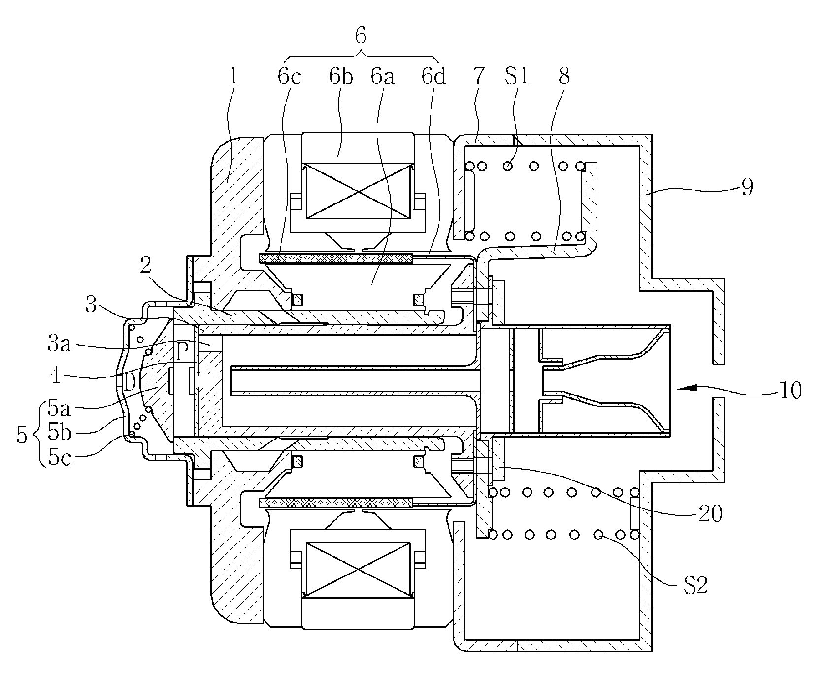
[0050]FIG. 6 illustrates a linear compressor in accordance with one embodiment of the present invention. One embodiment of a linear compressor 100 in accordance with the present invention includes a cylinder 200, a piston 300, a linear motor 400 provided with an inner stator 420, an outer stator 440, and a permanent magnet 460, and a mass member 900, each being housed in a shell 110 serving as a hermetic casing. When the permanent magnet 460 linearly reciprocates by an interactive electromagnetic force between the inner stator 420 and the outer stator 440, the piston 300 connected to the permanent magnet 460 engagedly moves along the permanent magnet 460, making a linear reciprocating movement.

[0051]The inner stator 420 is affixed to an outer periphery of the cylinder 200, and the outer stator 440 is secured axially by a frame 520 and a motor cove...


PUM


Abstract

A linear compressor comprises: a fixed member including a cylinder for providing a refrigerant compression space; a movable member, which includes a piston for compressing refrigerant inside the cylinder and a supporter composed of a center portion being aligned with a center of the piston and a support portion extended radially of the piston and which makes a linear reciprocating movement about the fixed member; a plurality of mainsprings supported on the support portion of the supporter, for elastically supporting the piston in an axial direction; and a mass member, which includes a center portion to couple with the center portion of the supporter and a plurality of ends extended from the center portion to maintain an air-gap towards the support portion of the supporter and towards the mainsprings. The linear compressor of the present invention can accommodate a maximum mass member in a defined space of a linearly reciprocating movable member, so material loss is prevented and more installation space can be secured.

Description

TECHNICAL FIELD[0001]The present invention relates in general to a linear compressor, and more particularly, to a linear compressor that can accommodate a maximum mass member in a defined space of a linearly reciprocating movable member.[0002]In addition, the present invention relates to a linear compressor featuring enhanced assembly efficiency of components that constitute the movable member.BACKGROUND ART[0003]In general, a reciprocating compressor is designed to form a compression space to / from which an operation gas is sucked / discharged between a piston and a cylinder, and the piston linearly reciprocates inside the cylinder to compress refrigerants.[0004]Most reciprocating compressors today have a component like a crankshaft to convert a rotation force of a drive motor into a linear reciprocating drive force for the piston, but a problem arises in a great mechanical loss by such motion conversion. To solve the problem, development of linear compressors is still under progress....

Claims


Application Information

Patent Timeline
Patent Type & Authority Applications(United States)
IPC IPC(8): F04B39/00F04B35/04
CPCF04B35/045F04B39/14
Inventor LEE, JONG-KOOHYEON, SEONG-YEOL
Owner LG ELECTRONICS INC
Why Eureka
Try Eureka