Methods and devices for deploying biological implants

a biological implant and implant technology, applied in the field of biological implant deployment methods and devices, can solve the problems of uneven wear of the ankle, loss of mobility of the ankle, cartilage erosion and subsequent break down of the subchondral bone, etc., and achieve the effect of low toleran

Inactive Publication Date: 2010-12-16
TALUS MEDICAL
View PDF8 Cites 201 Cited by
  • Summary
  • Abstract
  • Description
  • Claims
  • Application Information

AI Technical Summary

Benefits of technology

[0016]The osteotomes and guides can provide repeatable cuts with low tol

Problems solved by technology

Osteoarthritis or trauma can result in ankle pathology of uneven wear on, and/or direct trauma to, the surface of the talus.
This commonly leads to cartilage erosion and subsequent break down of subchondral bone.
This fusion procedure results in loss of mobility of the ankle, a

Method used


Image

  • Methods and devices for deploying biological implants
  • Methods and devices for deploying biological implants
  • Methods and devices for deploying biological implants

Examples


Embodiment Construction

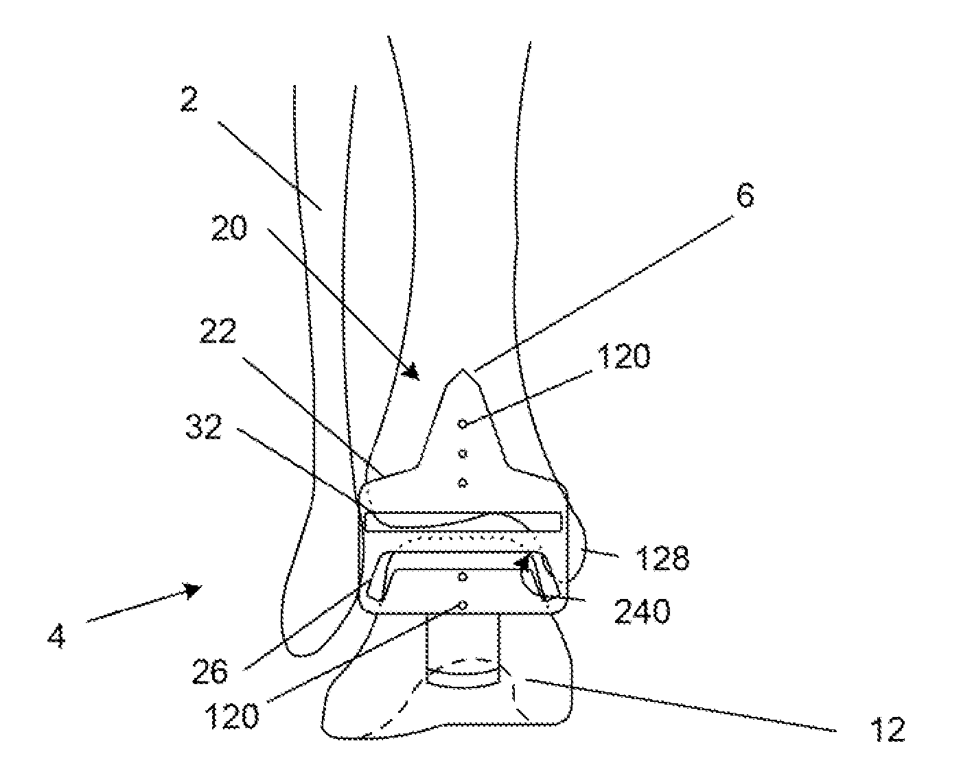
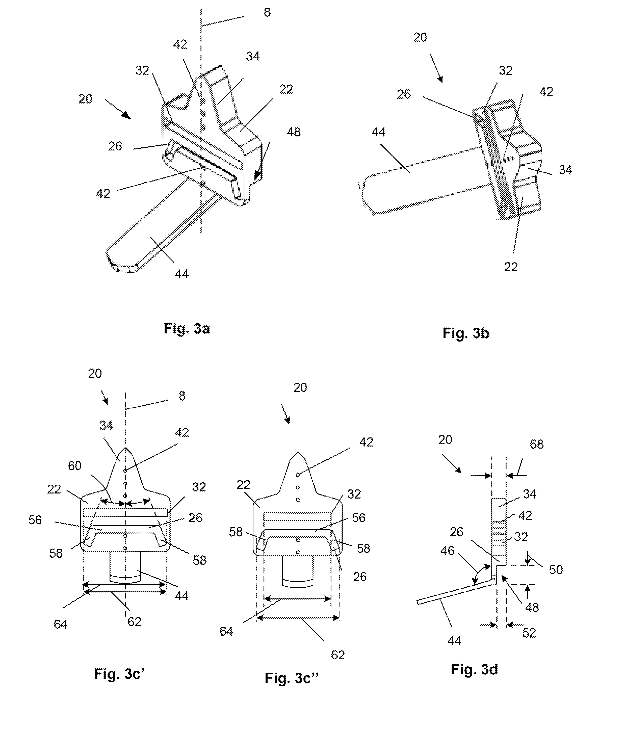
[0047]FIGS. 3a, 3b and 3d illustrate an osteotomy guide 20 that can have a guide body 22 having a guide body thickness 68. A talus port or slot 26 and / or tibia port or slot 32 can pass through the entire guide body thickness 68. The talus and tibia slots 26, 32 can be configured to receive and direct one or more osteotomes. The guide body 22 can have a narrowing guide neck 34 at the superior end of the guide body 22. The guide body 22 can have one, two or more alignment holes 42 passing through the entire guide body thickness 68. The alignment holes 42 can be configured in one or more lines, for example along a horizontally-centered, vertical axis 8. A superior end of the guide body 22 can narrow along the vertical axis 8 into a guide neck 34. The guide neck 34 can have additional alignment holes 42.

[0048]The guide body thickness 68 can be from about 6.4 mm (0.25 in.) to about 38 mm (1.5 in.), for example about 19 mm (0.75 in.). The guide body 22 can be sufficiently thick to prevent...


PUM


Abstract

Methods and devices for deploying biological implants are disclosed. The biological implants can include orthopedic, multi-component ankle implants. The target site can be prepared by fixing a rigid, alignable guide or jig with saw holes to the bone(s). Saws configured to fit through the saw holes can then be inserted through the saw holes to cut the bone(s). The jig can then be removed. Slidable implants can be positioned. Implants needing to be forced into place can be attached to elongated members to gently hold the implant and to provide a non-implant surface on which to apply the force.

Description

CROSS-REFERENCE TO RELATED APPLICATION[0001]This application is a continuation of PCT Application No. PCT / US2008 / 070441, filed 18 Jul. 2008, which claims the benefit of U.S. Provisional Application No. 60 / 951,120, filed 20 Jul. 2007, both of which are incorporated by reference herein in their entireties.FIELD OF THE INVENTION[0002]This invention relates to methods and devices for deploying biological implants, more specifically for methods and devices for deploying bone implants.BACKGROUND OF THE INVENTION[0003]FIGS. 1 and 2 illustrate anterior and lateral views of the tibia 6, talus 12 and fibula 2 (not shown in FIG. 2). A vertical axis 8 and an original talus thickness 10 are shown. The original talus thickness 10 is dependent on individual anatomical factors and the amount of pathological bone degradation. The talus has a talus head (caput tali) and talus neck (collum tali). The talus head has a rounded talus head crown.[0004]Osteoarthritis or trauma can result in ankle pathology...

Claims


Application Information

Patent Timeline
IPC IPC(8): A61F5/00A61F2/42
CPCA61B17/15A61F2/4606A61F2/4202
Inventor WARNE, JAMES BRIANDAVIS, KIRKCOREY, CRAIG J.PIMLOTT, RODERICK JAMESCHOI, GEORGE YOSEUNG
Owner TALUS MEDICAL
Why Eureka
Try Eureka