Linked coil formation device and method of forming linked coils

a technology of linked coils and formation devices, which is applied in the direction of magnets, magnetic bodies, other domestic objects, etc., can solve the problems of prone to coil arrangement variations, manufacturing work has become very cumbersome, and the core cannot be occasionally inserted into the coil, etc., to achieve the effect of improving processing/production efficiency and speeding up speed and efficiency

Active Publication Date: 2010-12-23
TAMURA KK
View PDF2 Cites 17 Cited by
  • Summary
  • Abstract
  • Description
  • Claims
  • Application Information

AI Technical Summary

Benefits of technology

[0013]According to the present invention, a first coil part is formed at one end part of a coil material in a first coil processing line, and subsequently thereto, a second coil part is formed at the other end of the coil material in a second coil winding processing line; in this duration, the coil material to which the first coil part is attached via a material transfer unit is continuously transferred to the second coil winding processing line; and therefore, the coil material is sequentially moved continuously in one direction from introduction to the end of processing of each coil, so that each coil can be processed speedily and efficiently. In addition, as described above, the material transfer unit is adapted to be compatible with the first and second coil winding processing lines that are disposed in parallel to each other, thus enabling the coil material having the first coil part that is formed in the first coil winding processing line to be smoothly and speedily transferred to the second coil winding processing line by means of the material transfer unit, so that processing / production efficiency of linked coils can be remarkably improved.

Problems solved by technology

On the other hand, in the aforementioned coils of the prior art, since the end parts of the wires on the linking sides in the two coils are linked with each other via the communication terminal, variation is prone to occur to coil arrangement, and the core cannot be occasionally inserted into the coil.
In addition, in the coils of Patent Document 1, there is a need for a work of releasing the coat of each wire or the linking-side end part of the communication terminal for connection between each of the coils and the communication terminal, followed by welding the released part, and as a result, a manufacturing work has become very cumbersome.
Further, the two coils that are formed by their individual wires are electrically connected to each other by means of welding via the communication terminal; therefore, reliability of the welding part becomes unavoidably problematic; and further, there has been a problem that variation occurs to electrical characteristics of the coils, depending upon the workmanship of welding.
In addition, there is a need for a space of a folding part, and there is apprehension that variation occurs to the electrical characteristics of the coils, depending upon the workmanship of folding.
Further, while there is no need for the step of connecting each of the coils and the communication terminal, there is a need for the above-mentioned process of operation for folding, and a problem that the manufacturing work becomes cumbersome can arise, accordingly.
In addition, while the technique of forming two coils from one wire rod is disclosed in Patent Documents 3 to 6 and the method of forming these coils is disclosed in Patent Documents 7 and 8, the method of forming these coils causes a problem.
Therefore, if the formation technique of Patent Documents 7 and 8 or the like is employed, while two coils can be formed without an occurrence of an inter-coil displacement in an ideal state, a problem still remains unsolved in applying this technique to an actual manufacturing process.

Method used


Image

  • Linked coil formation device and method of forming linked coils
  • Linked coil formation device and method of forming linked coils
  • Linked coil formation device and method of forming linked coils

Examples


first embodiment

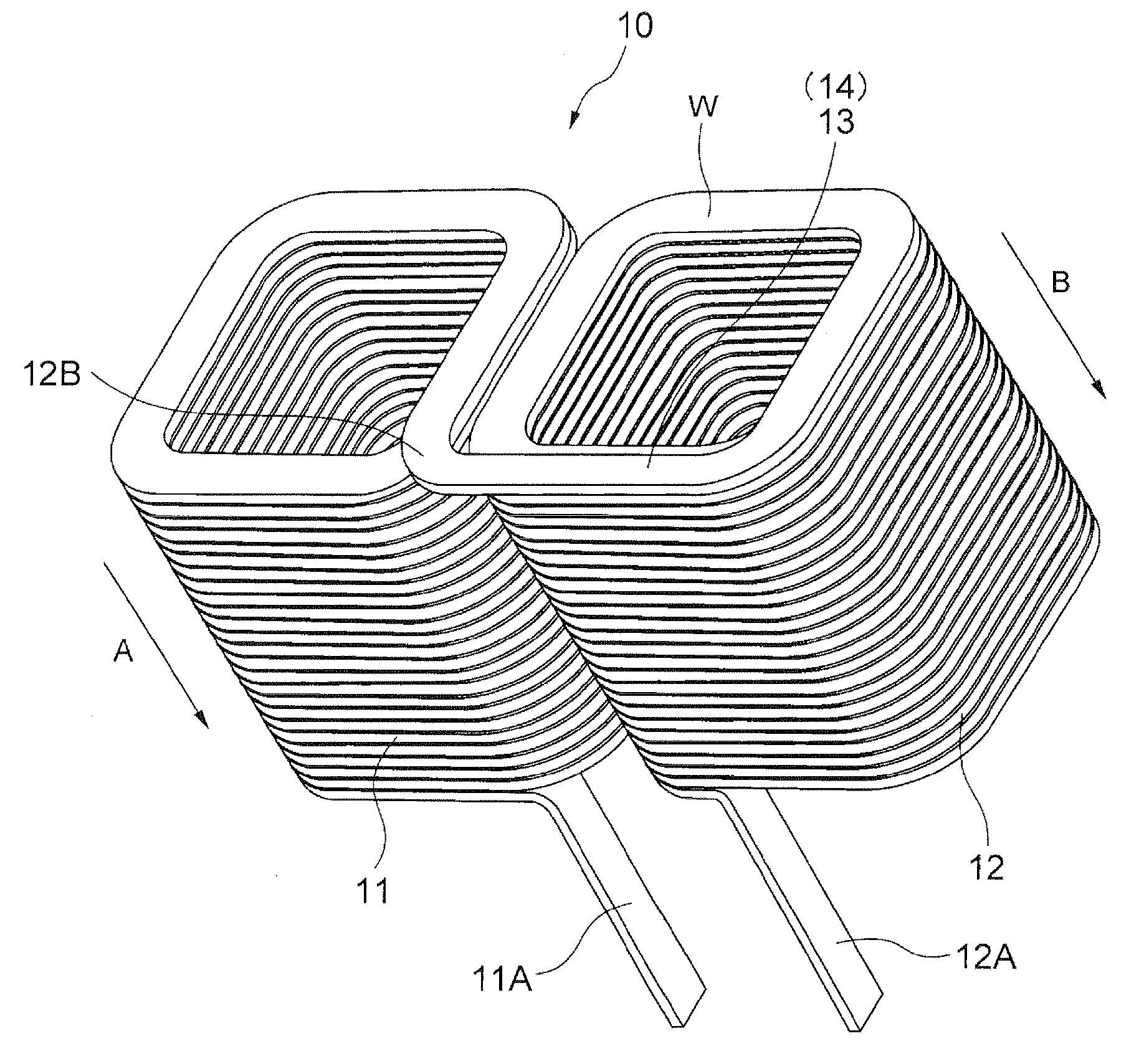
[0110]On the other hand, a coil displacement Y is positionally corrected so as to be zero in winding operation in short of two turns in the final step, i.e., so that the first and second coil parts 11 and 12 are arranged without being displaced from each other. The coil displacement Y is due to accumulation of a feed error, etc., of the flat wire W in the second coil winding step. In the method of forming linked coils by the linked coil formation device of the first embodiment, a distance from an arbitrary reference position to the first coil part 11 is measured at a time point while in the second coil winding; an offset part which is an adjustment substitute in accordance with the distance data is formed, thereby eliminating an accumulated error leading up to the time point of the second coil winding. Although this distance measurement must be executed at a position in short of two turns of the final step in which a position correction operation is to be performed, the measurement ...

second embodiment

[0152] as described above, in addition to the effects (1) to (5) or similar, the following effects are attained.

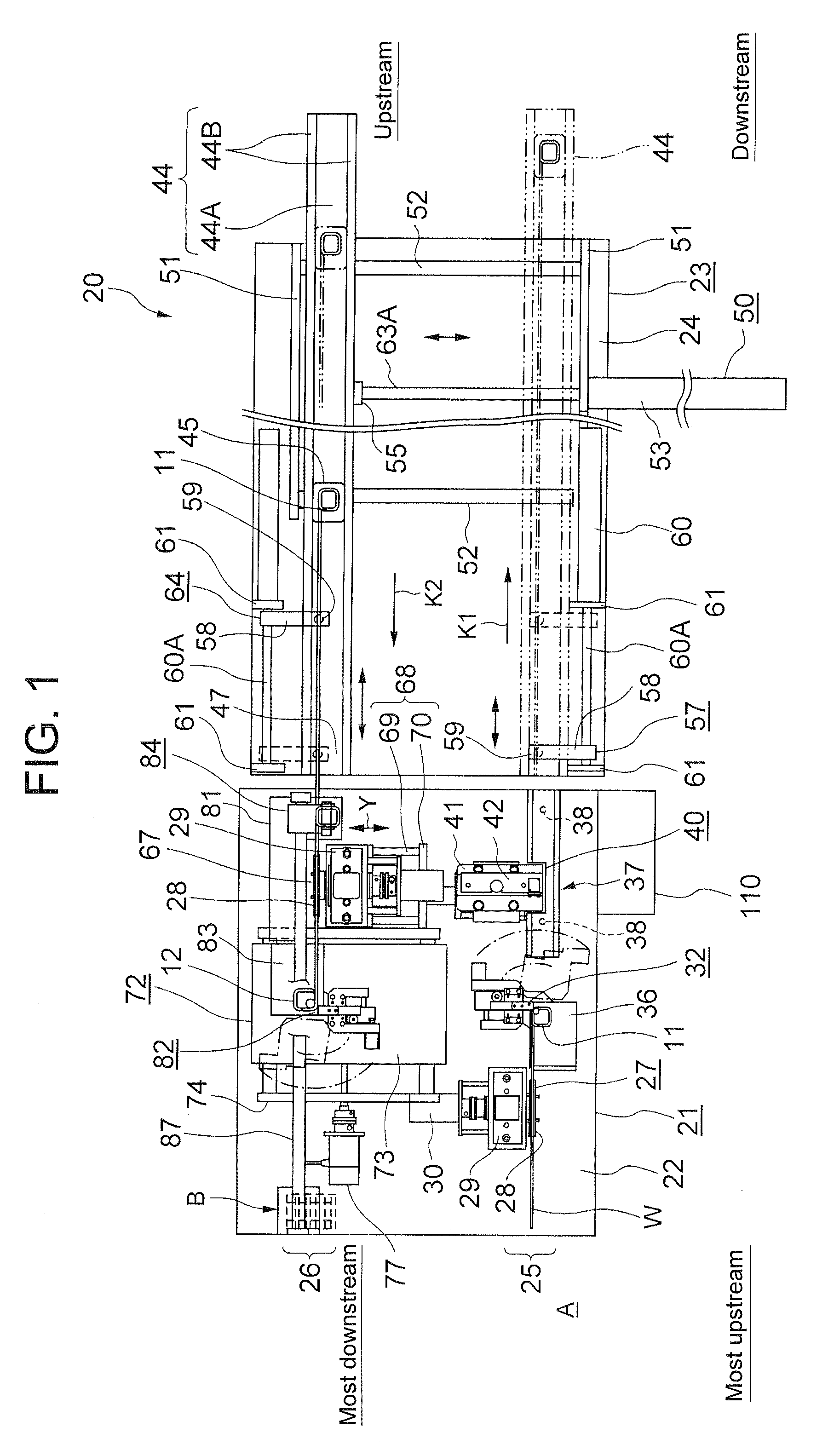
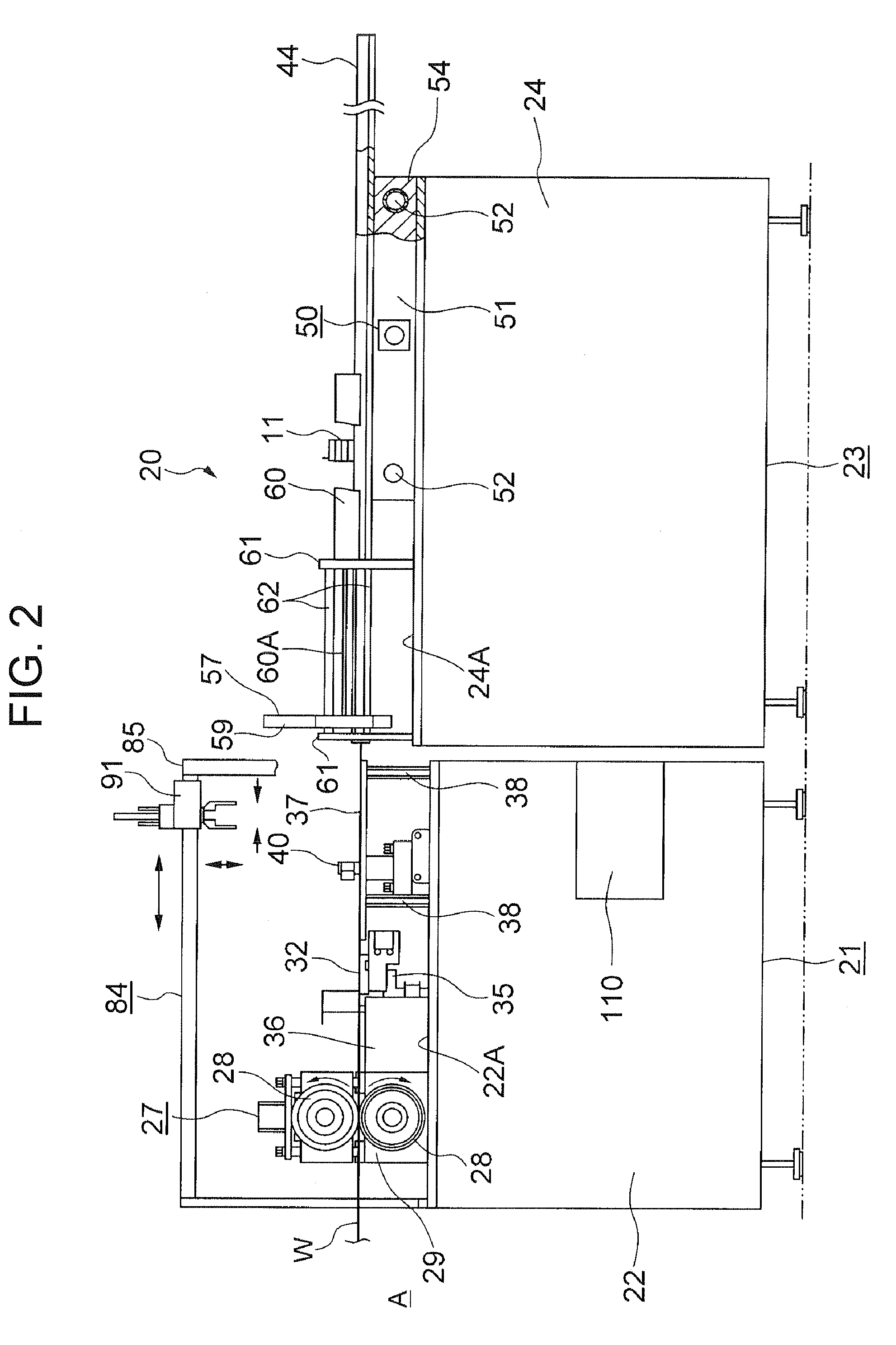
(6) A lead part 11A of a first coil part 11 and a lead part 12A of a second coil part 12 are bent to be erected in the direction that is substantially orthogonal to a flat face of a flat wire W, respectively, by means of a first forming unit 121 and a second forming unit 145 before winding processing of each of the coil parts 11, 12 is started, and in this state, winding processing is started. Therefore, even in the case of the final winding after advancement of the second coil part 12, the respective lead parts 11A, 12A do not interfere with the first and second coil parts 11 and 12, and a linked coil 10 with high winding precision can be thereby formed.

(7) The lead part 11A of the first coil part 11 and the lead part 12A of the second coil part 12 are allowed to be automatically bent, respectively, by the first forming unit 121 and the second forming unit 145, so that th...


PUM

PropertyMeasurementUnit
angleaaaaaaaaaa
angleaaaaaaaaaa
shapeaaaaaaaaaa

Abstract

[Problem to be Solved] A first coil and a second coil are efficiently formed in the shape of a rectangular cylinder and in parallel to each other, by bending and processing a flat wire, and a linking part of each of the coils, is linked with the same material without welding or folding.[Means for Solving the Problem] Provided are: a first coil winding processing line having a first winding head forming a first coil part in the shape of a rectangular cylinder at one end part of a flat wire W; a second coil winding processing line disposed in parallel to the first coil winding processing line and having a second winding head on which a second coil part in the shape of a rectangular cylinder is formed at the other end part of the flat wire W and both of the coil parts are arranged to be adjacent to each other on an identical face; and a coil placement unit for conveying the flat wire W having the first coil part from the first coil winding processing line to the second coil winding processing line along each coil winding processing line.

Description

TECHNICAL FIELD[0001]The present invention relates to a linked coil formation device and a method of forming linked coils, in particular to a linked coil formation device and a method of forming linked coils, which are suitable to be employed as reactor coils.BACKGROUND TECHNOLOGY[0002]A reactor is generally provided with a wire and a magnetic core, and an inductance is obtained by constituting a coil of which the wire is wound around the core. Conventionally, a reactor is employed in a step-up circuit, an inverter circuit, and an active filter circuit or the like. As such reactor, there has been often employed the one in which a core and a coil wound around the core are accommodated in a case made of a material such as a metal together with other insulation members or the like. In addition, in a reactor employed in a step-up circuit for vehicle-mounting, for example, two independent coils, each of which is formed by a predetermined winding diameter and the number of windings, are f...

Claims


Application Information

Patent Timeline
Patent Type & Authority Applications(United States)
IPC IPC(8): B21F3/00
CPCH01F41/0604Y10T29/49071H01F41/065H01F27/2847H01F41/061H01F41/071
Inventor HATTORI, KAORU
Owner TAMURA KK
Why Eureka
Try Eureka