
Displacement diffuser with heat/cool changeover

a diffuser and heat/cool technology, applied in lighting and heating apparatus, ventilation systems, heating types, etc., can solve the problems of reducing the overall relative ventilation efficiency, sharp drop in ventilation efficiency, and high concentration of contaminants near these sources, so as to maximize comfort in both heating and cooling modes, and consume minimal usable floor space. , the effect of easy installation and operation

Inactive Publication Date: 2010-12-23
RIMMER JULIAN
View PDF5 Cites 1 Cited by
  • Summary
  • Abstract
  • Description
  • Claims
  • Application Information

AI Technical Summary

Benefits of technology

[0018]The displacement diffuser produces a one-way low velocity air supply from a suspended ceiling installation. It discharges air evenly across the perforated face with minimal turbulence or induction of room air. The cool supply air flows from the ceiling, through the low velocity air outlet, and down to the floor level to gradually fill the space. It can be installed in a standard suspended ceiling, freeing up valuable floor space, and reducing needed ducting.
[0020]Conditioned air is supplied to the displacement diffuser of the present invention via a ducted connection. The dual plenum is tightly sealed to ensure optimum operation in a pressurized environment. The ceiling-mounted location of the device allows for both efficient and effective mixing and induction ventilation, while freeing up valuable floor space needed for conventional systems.
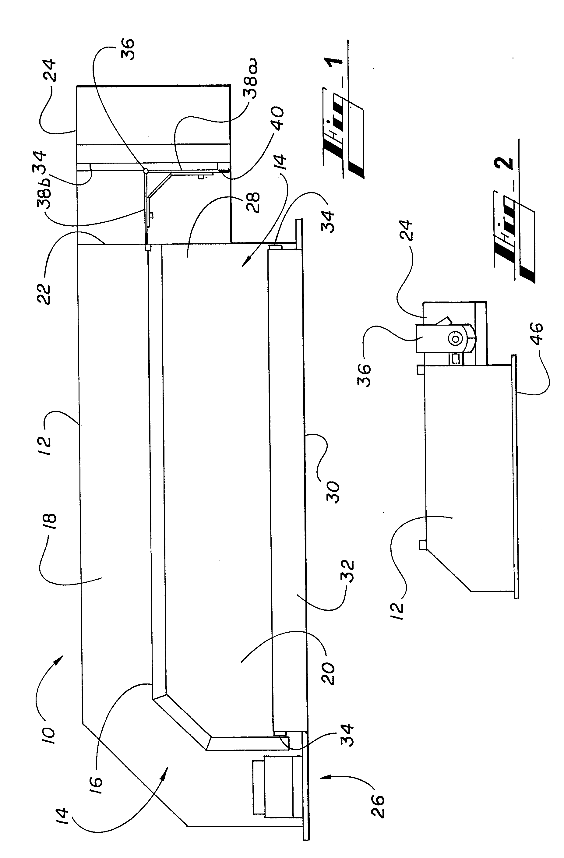
[0022]The cooling plenum is constructed with an equalization baffle behind the operative perforated diffuser face for uniform, low velocity distribution of supply air. Both the equalization baffle and the perforated diffuser face are securely fastened to the diffuser frame of the housing. The diffuser frame ensures the rigidity and positioning of the equalization baffle. The heating plenum has a linear air slot diffuser which can be constructed of heavy wall extruded aluminum air deflector frames.
[0024]One feature of the present invention is a simple device that allows for the heating and cooling of a variety of configurations of an occupied space having various contaminant loads and rates of movement within the space. Another feature of the present invention is that it is compact, easy to install and operate, and compatible with both heating and cooling functions in the same unit. Another feature of the present invention is that the displacement diffuser is capable of changing its air circulation method from displacement ventilation to mixing ventilation to maximize comfort in both a heating and a cooling mode. Yet another feature of the present invention is that it ensures a comfortable environment for building occupants who are highly sensitive to drafts that may pass over their body from overhead high velocity airstreams. Yet another feature of the present invention is a single device that overcomes the challenges of flow velocities needed when supplying a space with hot air such that the supply air has enough forward momentum to overcome the effects of buoyancy while providing a comfortable environment. Yet another feature of the present invention is a ventilation device that consumes minimal usable floor space within a room. Still another feature of the present invention is a ventilation device having a dual plenum that fits easily into a ceiling grid yet is adaptable for mounting in unique mounting spaces.

Problems solved by technology

Unless the sources of contamination are evenly distributed throughout the space, however, high concentration levels of contaminants are always found near these sources.
Because the conditioned air is usually supplied at a high level (above the occupied zone), the concentration levels above the occupied zone are generally lower than those existing within the zone, which results in a lower overall relative ventilation efficiency.
In addition, stagnant zones of high concentration levels and / or short circuiting of conditioned air to extract points can cause a sharp drop in the ventilation efficiency.
If obstructions such as furniture or partitions are encountered, the air will flow around and beyond the obstruction.
Supplying a space with hot air at the same flow velocities required by displacement ventilation is not generally recommended because the supply air does not have enough forward momentum to overcome the effects of buoyancy, and will rise to the ceiling level and be exhausted or returned, bypassing the occupied zone.
Although displacement ventilation systems seem to be, in principle, more effective at meeting ventilation needs than the equivalent mixing approach, air cooling or heating capacity is limited by nature of the need for careful thermal control of the supply air temperature.
Further, unlike mixing ventilation, the spatial concentration of pollutant within an occupied space is non-uniform, with air upstream of the pollutant source being uncontaminated while the air downstream of source may be heavily contaminated.
Displacement ventilation alone also can produce a high concentration level of airborne contaminants.
If the return air is located below the ceiling, the air above the return may not be exhausted properly from the space and polluted or hot air may remain in the occupied zone.
Thus, conventional diffuser systems take up considerable space both at the floor level, where the supply air enters the room, and at the ceiling level for the return air.
While this typical system has a mechanism for changing the momentum of the discharge air from low in cooling mode to high in heating mode, it lacks the ability to change the air distribution method from displacement ventilation.
Although using a displacement ventilation method for both heating and cooling may be ideal for removing pollutants from the environment in industrial applications, the relative inflexibility of the conventional “displacement-only” heating / cooling system makes it inappropriate for use outside of industrial spaces.
The velocity and air pattern caused by the supporting jet make it unsuitable for use in areas where thermal comfort is a priority, like offices, theaters and the like.
Finally, there is a need for such a device that consumes minimal usable space within a room.

Method used


Image

  • Displacement diffuser with heat/cool changeover
  • Displacement diffuser with heat/cool changeover
  • Displacement diffuser with heat/cool changeover

Examples


Embodiment Construction

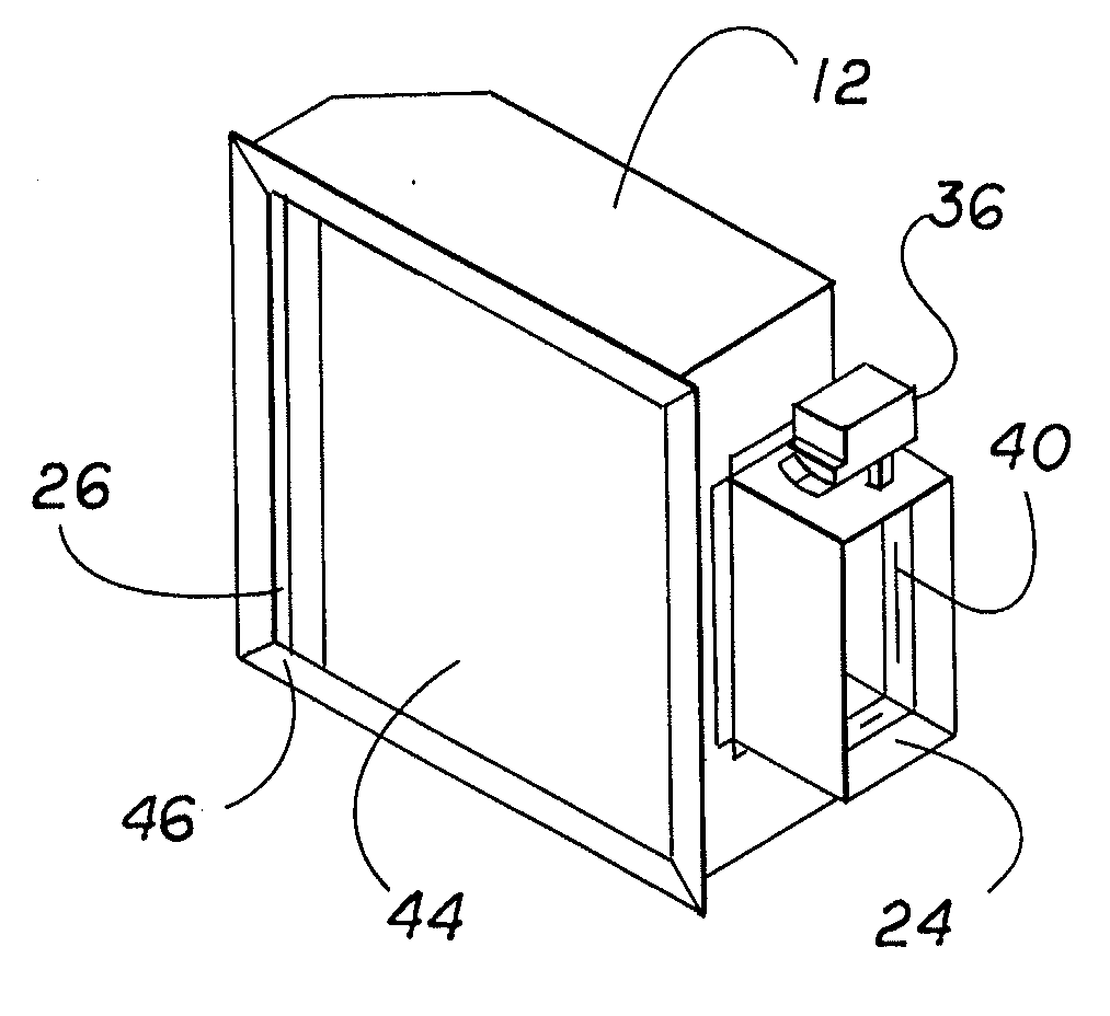
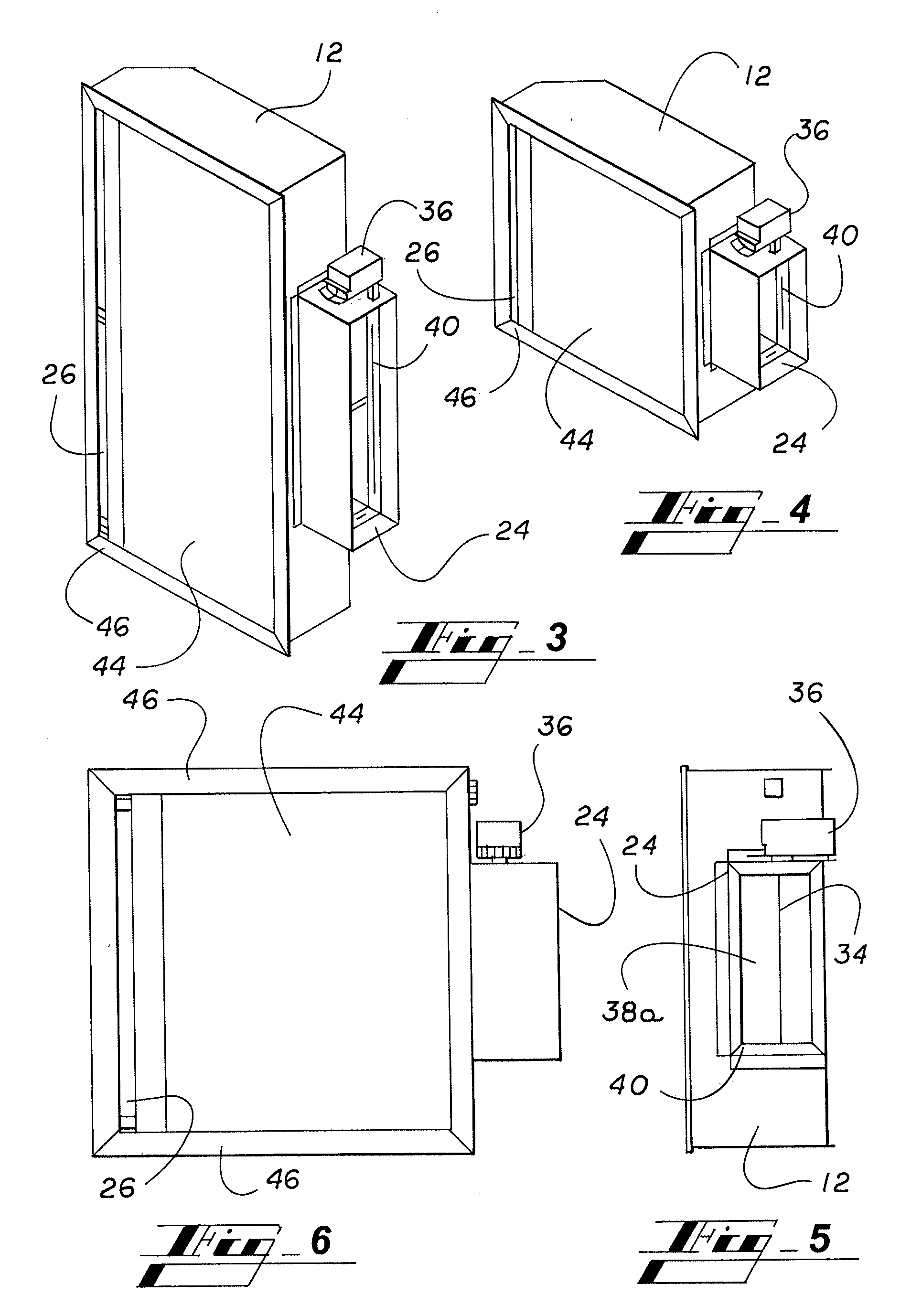
[0035]Illustrative embodiments of a device according to the present invention are shown in FIGS. 1 through 6. FIG. 1 cross-sectional side view of an embodiment of the displacement diffuser with a heating and cooling function in accordance with the present invention. FIG. 2 is a side elevation view of an embodiments of the displacement diffuser with a heating and cooling function in accordance with the present invention showing the exterior of the diffuser of FIG. 1, and detailing the control mechanism. FIGS. 3 and 4 are corner perspective views of the bottom and sides of two embodiments in different dimensions of a displacement diffuser with a heating and cooling function in accordance with the present invention in which an internal gasket can be seen in the duct housing. FIG. 5 is a side view of an embodiment of the displacement diffuser with a heating and cooling function in accordance with the present invention from an end of the diffuser containing the duct housing, the pivoting...


PUM


Abstract

A displacement diffuser mounted in a suspended ceiling installation for supplying both heated and cooled air and using both displacement and mixing ventilation within an occupied space from a single unit. The diffuser includes a housing, an air inlet in the housing in communication with supply air, and a dual plenum divided by an intermediate wall into a heating plenum for receiving heated air and a cooling plenum for receiving cooled air. A high velocity linear air slot diffuser in directs air from the heating plenum into an occupied space at a high velocity. A low velocity diffuser allows cooled air to move via displacement into an occupied space. A damper within the housing is capable of directing heated air into the heating plenum and cooled air into the cooling plenum in response to an actuator signal.

Description

CROSS-REFERENCE TO RELATED APPLICATIONS[0001]This application claims the benefit of U.S. Provisional Application No. 61 / 218,575, filed Jun. 19, 2009, which is incorporated herein by reference in its entirety.BACKGROUND OF THE INVENTION[0002]1. Technical Field[0003]This invention relates to a displacement diffuser for providing both heating and displacement cooling functions with minimal turbulence or induction of room air from the same unit. The displacement diffuser is capable of disbursing conditioned air using two different disbursement methods, and is used in connection with a ducted air conditioning and heating system. The displacement diffuser provides a dual plenum with a high velocity linear air slot diffuser for heated air, and a low velocity diffuser for cooled air and is capable of both displacement and mixing ventilation. The system switches from cooling to heating mode via an electronic actuator or a signal activated by duct temperature from the HVAC system.[0004]2. Pri...

Claims


Application Information

Patent Timeline
IPC IPC(8): F24F7/00
CPCF24F13/06F24F2221/14F24F13/26
Inventor RIMMER, JULIAN
Owner RIMMER JULIAN
Learn More