Structure for supporting electric power transmission lines

a technology for supporting structures and transmission lines, applied in the direction of buildings, buildings, constructions, etc., can solve the problems of increasing affecting the use of this kind of structure, and having low torsional resistance, so as to improve stress and strain behaviour, improve torsional and bending moments, and improve mechanical strength

Active Publication Date: 2010-12-23
SECCIONAL BRASIL SA
View PDF32 Cites 24 Cited by
  • Summary
  • Abstract
  • Description
  • Claims
  • Application Information

AI Technical Summary

Benefits of technology

[0019]The present invention has several advantages over the prior art. The use of a metallic vertical structure with general opposite frustum shapes with side supporting elements bellow the line supporting members allows the obtaining of a better stress and strain behaviour. This better behaviour is obtained due to the increased mechanical strength in view of the connection between the larger ends of the opposite frustums operating in conjunction with the side supporting elements, in order to resist against buckling due t

Problems solved by technology

Although metallic monopoles have some advantages, there are still considerable constraints to a wider use of this kind of structure.
The alternative structures proposed by GUNGER in the articles mentioned supra, as they do not use tubes, have generally the disadvantage of having low torsional resistance.
. . ] 220 kV’, in FIG. 1, which shows guys attached below the largest diameter of the vertical structure, also have some disadvantages, such as: increase of torsional and bending moment in operational conditions due t

Method used


Image

  • Structure for supporting electric power transmission lines
  • Structure for supporting electric power transmission lines
  • Structure for supporting electric power transmission lines

Examples


Embodiment Construction

[0023]This invention is not limited in its application to the details of construction and the arrangement of components set forth in the following description or illustrated in the drawings. The invention is capable of other embodiments and of being practiced or of being carried out in various ways. Also, the phraseology and terminology used herein is for the purpose of description and should not be regarded as limiting. The use of ‘including’, ‘comprising’, or ‘having’, ‘containing’, ‘involving’, and variations thereof herein, is meant to encompass the items listed thereafter and equivalents thereof as well as additional items.

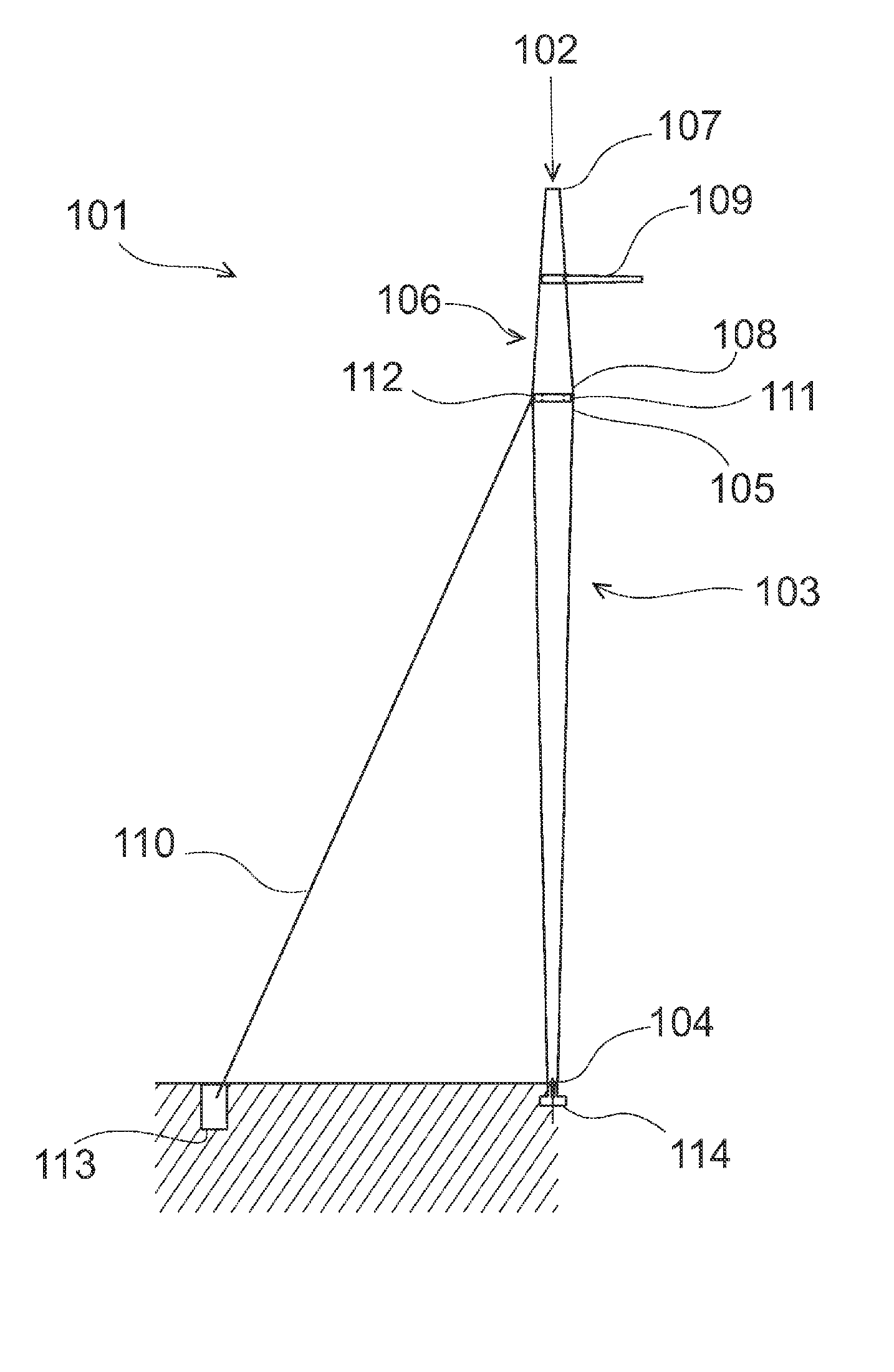
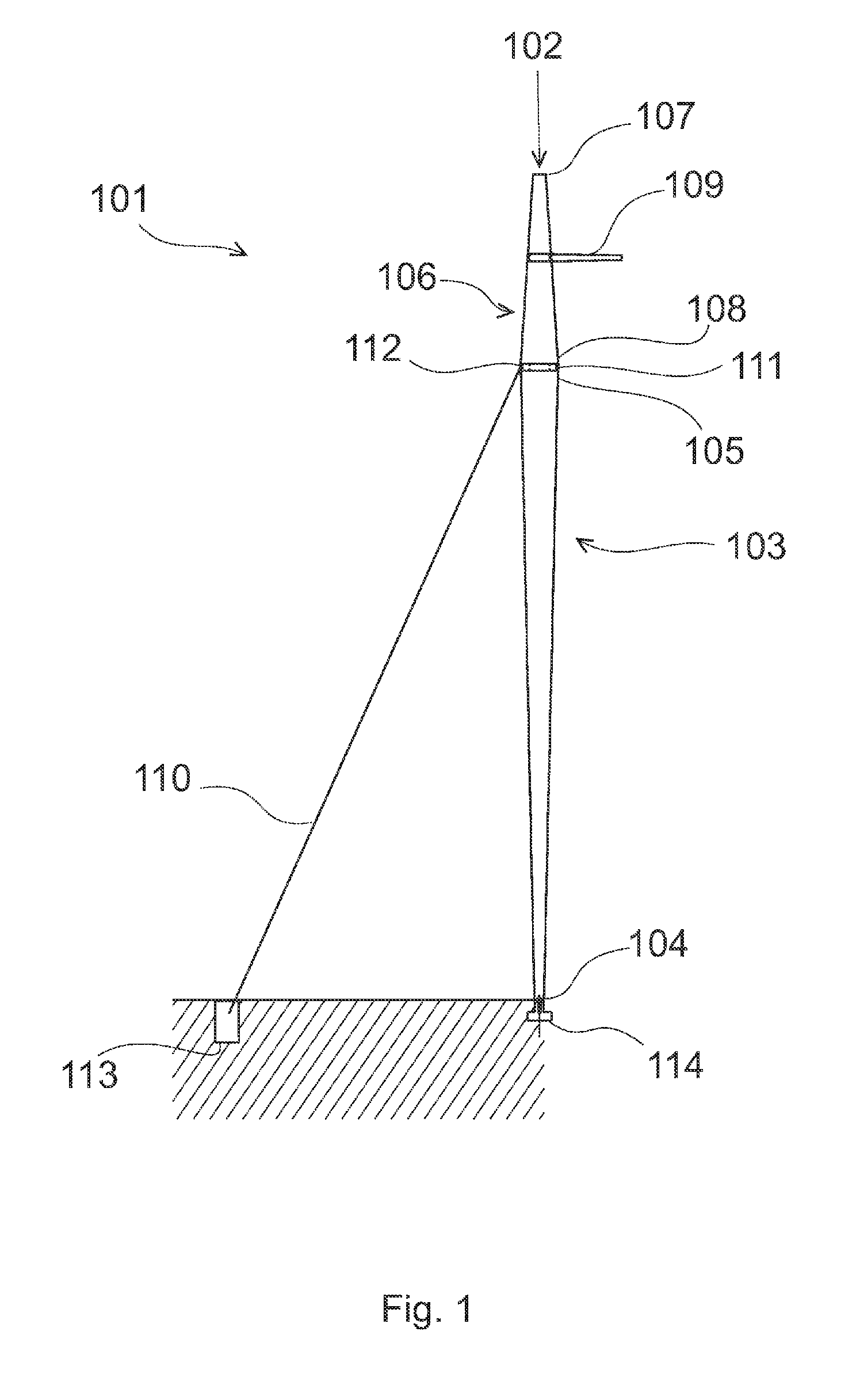
[0024]FIG. 1 illustrates one exemplary embodiment of the present invention, more particularly a structure (101) for supporting electric power transmission lines characterized by comprising a metallic vertical structure (102) having: a lower tubular frustum (103) shape with a smaller end (104) and a larger end (105), wherein the smaller (104) end is on the bot...


PUM


Abstract

A structure for supporting electric power transmission lines that aims to obtain a better stress and strain behaviour providing a higher ultimate economy. The preferred embodiment is directed to a structure that comprises a metallic vertical structure (101) having: a lower tubular frustum shape (103) with a smaller end (104) and a larger end (105), wherein the smaller end is on the bottom and the larger end on the top; an upper frustum shape (106) with a smaller end (107) and a larger end (108), wherein the smaller end is on the top and the larger end on the bottom; and wherein the larger end of the lower frustum is adjoined to the larger end of the upper frustum; line supporting members (109); side supporting elements (110) attached in the adjoining region (111) of the lower and upper frustums, and extending between the attachment and an anchoring base (113); and wherein the adjoining region is below the line supporting members.

Description

TECHNICAL FIELD[0001]This invention relates to vertical structures, such as towers, masts, poles or the like, particularly for use for supporting transmission lines of an electric power transmission system.BACKGROUND ART[0002]Towers, masts, poles or the like (hereinafter simply called ‘vertical structure(s)’) are well know in the prior art. Each single structure, due to the complexity of the loads being applied and due to other factors, is generally custom designed to the customer's specific requirements (e.g. the owner of the structure, such as an electric power distribution company). In the case of structures for supporting transmission lines of an electric power transmission system, in addition to the vertical structure itself, they also comprise braces, arms or similar members to which the overhead conductors are connected; as well as other accessories and components suitable for the desired purposes. A general overview of the related art may be found, for instance, in the book ...

Claims


Application Information

Patent Timeline
IPC IPC(8): E04H12/20E04H12/08
CPCE04H12/20
Inventor DE ABREU, PAULO EMMANUELDE ABREU, JR., PAULO EMMANUEL
Owner SECCIONAL BRASIL SA
Why Eureka
Try Eureka