Piezoelectric-ferroelectric actuator device

a technology of piezoelectric actuators and actuators, applied in piezoelectric/electrostrictive/magnetostrictive devices, piezoelectric/electrostriction/magnetostriction machines, electrical apparatus, etc., can solve the problems of nonlinear complex elation, non-monotonic and hysteretic, and traditional actuation devices do not operate in this rang

Active Publication Date: 2010-12-23
TECHNION RES & DEV FOUND LTD
View PDF9 Cites 8 Cited by
  • Summary
  • Abstract
  • Description
  • Claims
  • Application Information

AI Technical Summary

Benefits of technology

[0013]According to some embodiments of the invention the voltages inducing the nonlinear ferroelectric effect are applied momentarily.
[0014]According to some embodiments of the invention the at least one layer is applied by a voltage inducing a nonlinear ferroelectric effect in the layer, and at least one layer is applied by a voltage inducing a linear inverse piezoelectric effect in the layer.
[0015]According to some embodiments of the invention the voltage inducing the nonlinear ferroelectric effect is applied momentarily, and the voltage inducing the linear inverse piezoelectric effect is applied continuously.
[0016]According to some embodiments of the invention a number of layers applied by the voltage inducing the linear inverse piezoelectric effect is selected so as to compensate a minimal discontinuous displacement generated by the nonlinear ferroelectric effect.
[0017]According to some embodiments of the invention the actuator device further comprises a loop control unit for controlling voltages applied to induce the linear inverse piezoelectric effect in response to displacements generated by the nonlinear ferroelectric effect.
[0018]According to some embodiments of the invention the method further comprises controlling voltages applied to induce the linear inverse piezoelectric effect according to displacements generated by the nonlinear ferroelectric effect.

Problems solved by technology

These complex elations are nonlinear, non-monotonic and hysteretic.
Thus, although relatively large strains can evolve within the ferroelectric range, traditional actuation devices do not operate in this range since the nonlinear behavior and discontinuous variations are hard to be controlled.

Method used


Image

  • Piezoelectric-ferroelectric actuator device
  • Piezoelectric-ferroelectric actuator device
  • Piezoelectric-ferroelectric actuator device

Examples


example 1

Exemplified Operation Scheme

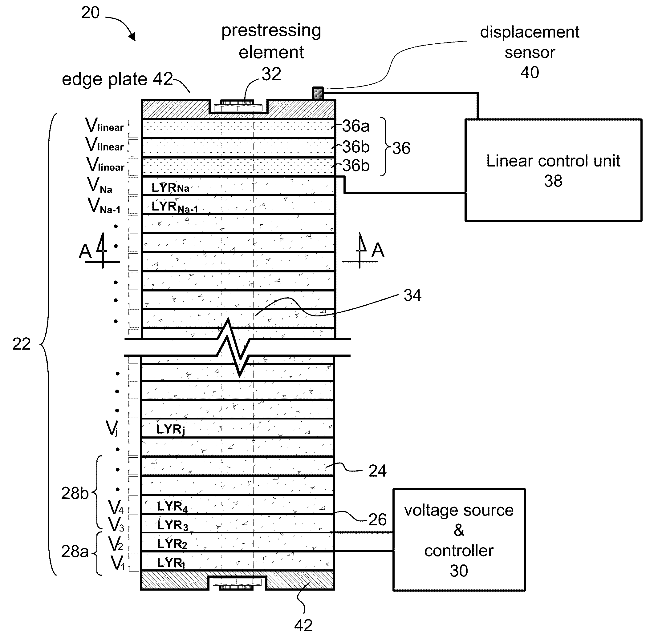
[0129]The present example describes a method which can be used according to some embodiments of the present invention for determining an operation scheme of the actuator device. The operation scheme can include the voltage applied to each layer or group of layers (e.g., sub-stacks) such that the overall displacement at the tip of the actuator is u3d.

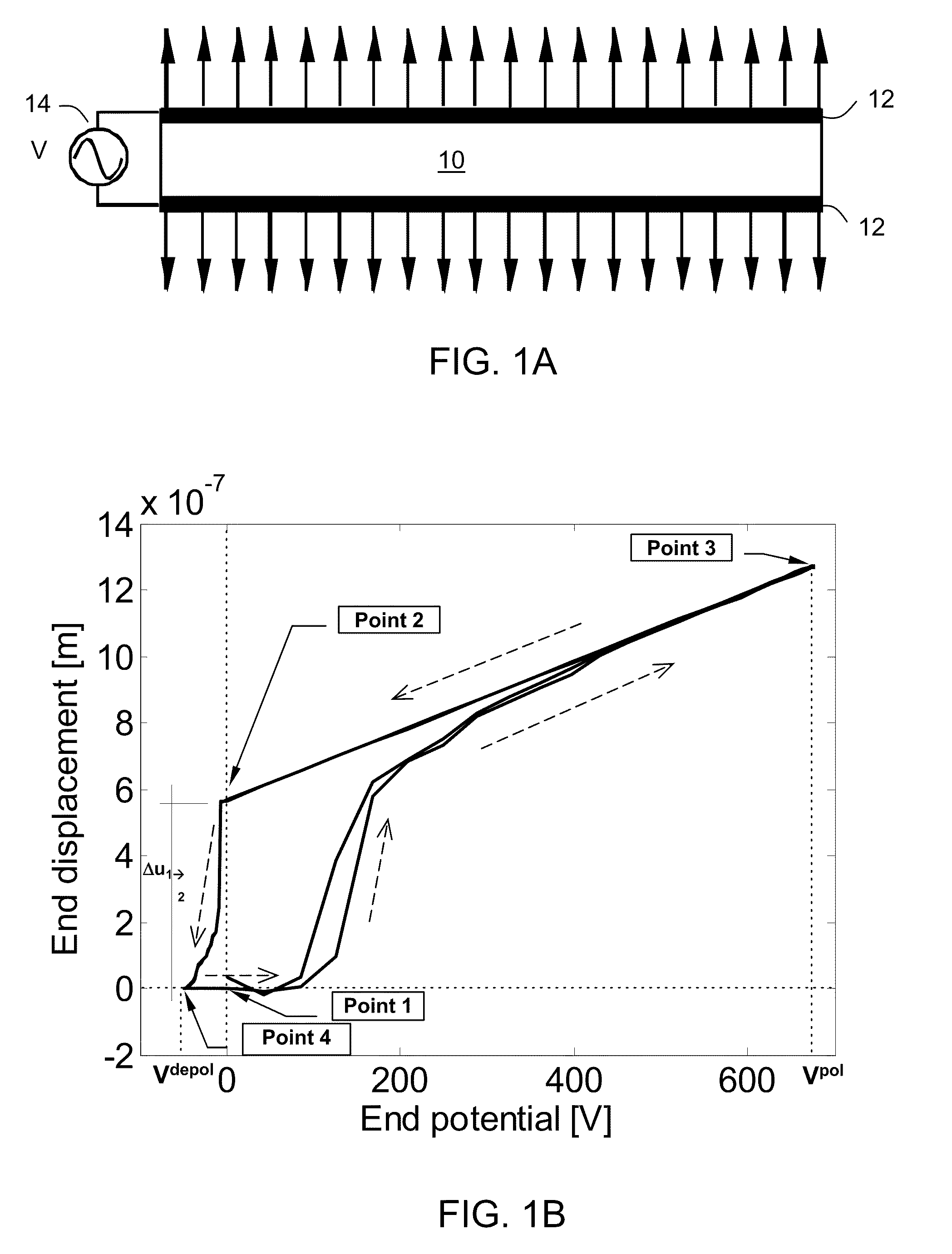
[0130]The method begins by determining the optimal domain state of each layer or sub-stack, and assigning for each layer or sub-stack a working point which corresponds to a domain state. In the present example, the working points correspond to a depoled domain state with zero applied voltage and a fully polarized domain state with zero applied voltage (see, e.g., Points 1 and 2 of FIG. 1B). These working points are referred to hereinunder as working point 1 and working point 2, respectively.

[0131]Once the working points are assigned, the method determine, for each layer or sub-stack which is assigned with a wo...

example 2

Numerical Study

[0142]In the present example, the method described in Example 1 was employed to study the operation of an actuator device according to some embodiments of the present invention. The properties and components of the actuator device studied in this example are summarized in Table 1, below:

TABLE 1PropertySymbolValueNumber of individually controlled activeNa400layersNumber of layers in the linear partNLin 3Depoled layer thicknessl0.25[mm]Radius of the actuatorR20[mm]Radius of the rubber pre-stressingr2.167[mm]elementElastic modulus of an active layer at[C3333]134[GPa]working point 1Elastic modulus of an active layer at[C3333]234[GPa]working point 2Axial piezoelectric constant of the lineard333−1.049 * 10−6[mm / V]segmentLayer thickness change when switchingΔu1→25.3996E * 10−4[mm]from point 1 to 2Pre-stressing element's elastic modulusEps2800[MPa]Prestressing forceΛ33019872[N]Prestressing stressΛ330 / πr216[MPa]Spring Constant of the pre-stressing elementKp=πr2Eps(Na+NLin)l410...

case 1

Electrical Actuation

[0187]The first numerical example studies the active layer shown in FIGS. 8A-B, with λ3=0 and Λ33=0 (i.e. electrical load only). The non-linear response of the actuator, the response to the high-level electrical load (±1.5 [kV]) predicted by the linear theory, and the response to the low-level electrical load within the linear range (±0.25 [kV]) predicted by the nonlinear theory appear in FIGS. 9A-D. FIGS. 9A and 9B show that the displacement range observed under voltage applied in the nonlinear regime is about 4 times larger than the displacements under a voltage difference in the linear operational range. This is a notable improvement of the actuation capabilities. FIGS. 9A-D also show that the prediction of the linear theory is fundamentally different from the actual nonlinear response. At some instances, the linear theory fails to predict the magnitude and the sign of the response. It should be noted, however, that the linear range of operation can be extende...


PUM


Abstract

An actuator device is disclosed. The actuator device comprises a stack of piezoelectric-ferroelectric active layers separated by surface electrodes. At least a few of the surface electrodes are independently addressable such that at least two active layers are biasable by different voltages. In an embodiment of the invention, at least a few of the voltages induce a nonlinear ferroelectric effect.

Description

RELATED APPLICATION / S[0001]This application claims the benefit of priority from U.S. Patent Application No. 61 / 023,983, filed Jan. 28, 2008. The contents of U.S. Patent Application No. 61 / 023,983 are incorporated by reference as if fully set forth herein.FIELD AND BACKGROUND OF THE INVENTION[0002]The present invention, in some embodiments thereof, relates to an actuator and, more particularly, but not exclusively, to a piezoelectric-ferroelectric actuator device operating, at least in part, in the nonlinear ferroelectric range.[0003]An actuator is a mechanical device for moving or controlling another device. The actuator generally provides force or motion in response to an applied stimulus. Many commonly used actuators are inductive in nature. However, from a purely theoretical point of view, piezoelectric actuators, which are capacitive in nature, exhibit much more desirable mechanical and electrical characteristics. Piezoelectric materials are characterized by an ability to deform...

Claims


Application Information

Patent Timeline
Patent Type & Authority Applications(United States)
IPC IPC(8): H01L41/083H01L41/047H01L41/09
CPCH02N2/062H01L41/042H01L41/0833H01L41/0825H01L41/0536H10N30/802H10N30/886H10N30/1071H10N30/503
Inventor KUSHNIR, URIRABINOVITCH, ODED
Owner TECHNION RES & DEV FOUND LTD
Why Eureka
Try Eureka