
Multicast service provision in a mobile communication system having overlapping pool areas

a mobile communication system and multicast service technology, applied in broadcast service distribution, data switching networks, high-level techniques, etc., can solve the problems of loss of multicast service for the remaining terminals attached to the other pool area, waste of network resources, and inability to inherently support point-to-multipoint services like multicast or broadcast, etc., to facilitate efficient resource utilization

Inactive Publication Date: 2010-12-23
SOVEREIGN PEAK VENTURES LLC
View PDF2 Cites 88 Cited by
  • Summary
  • Abstract
  • Description
  • Claims
  • Application Information

AI Technical Summary

Benefits of technology

[0035]One object of the invention is to suggest a mechanism that facilitates efficient resource utilization in the distribution of service data to access nodes (e.g. eNode Bs) that are located in an overlapping region of pool areas.
[0036]Another object of the invention is to enable service continuity of a multicast service received by a mobile terminal in a communication network where access nodes may be assigned to several pool areas simultaneously. Another object of the invention is to improve the management of the user plane in a communication network, where access nodes may be assigned to several pool areas simultaneously.
[0043]Both aspects outlined above may be readily combined so as to enable service continuity and efficient resource utilization in the overlapping part of pool areas simultaneously.
[0095]In another embodiment, relates to an approach of centrally registering user plane entities that established a user plane for a particular service. This central “register” could be for example maintained in a core network entity, for example a BM-SC for MBMS services. For an effective implementation, it may be advantageous, if access nodes assigned to the first and the second pool area simultaneously are assigned to a separate tracking area and the query indicates said separate tracking area. Generally, controlling and updating registrations of mobility management entities on a tracking area level may be advantageous, as tracking area updates may be used as triggers for checking the mobility entity's registration at the user plane entity for a service and potentially updating or establishing a registration.

Problems solved by technology

However, they usually do not inherently support point-to-multipoint services like multicast or broadcast.
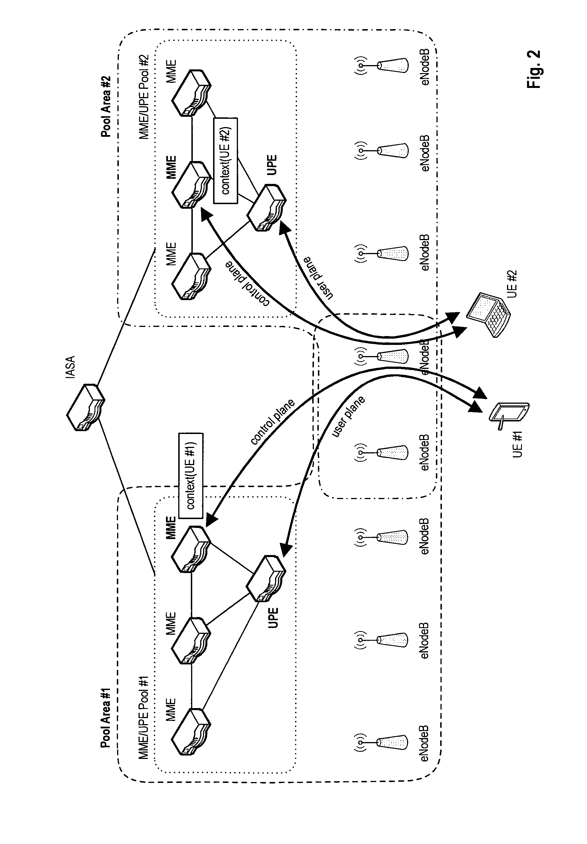
However, for multicast services there is no direct relation between the mobile terminal and the M-UPE, i.e. the terminal does not maintain a user plane bearer to the M-UPE.
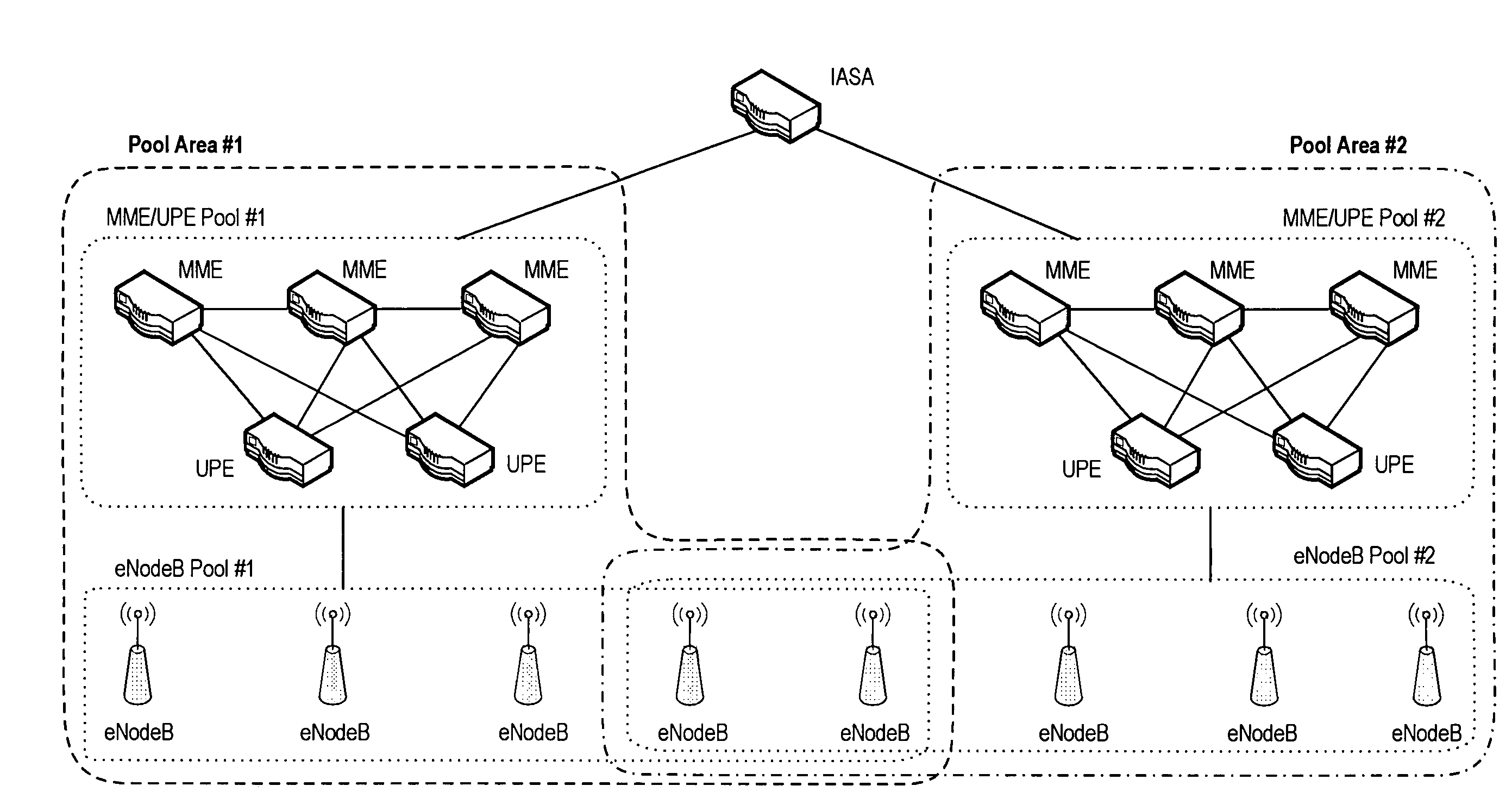
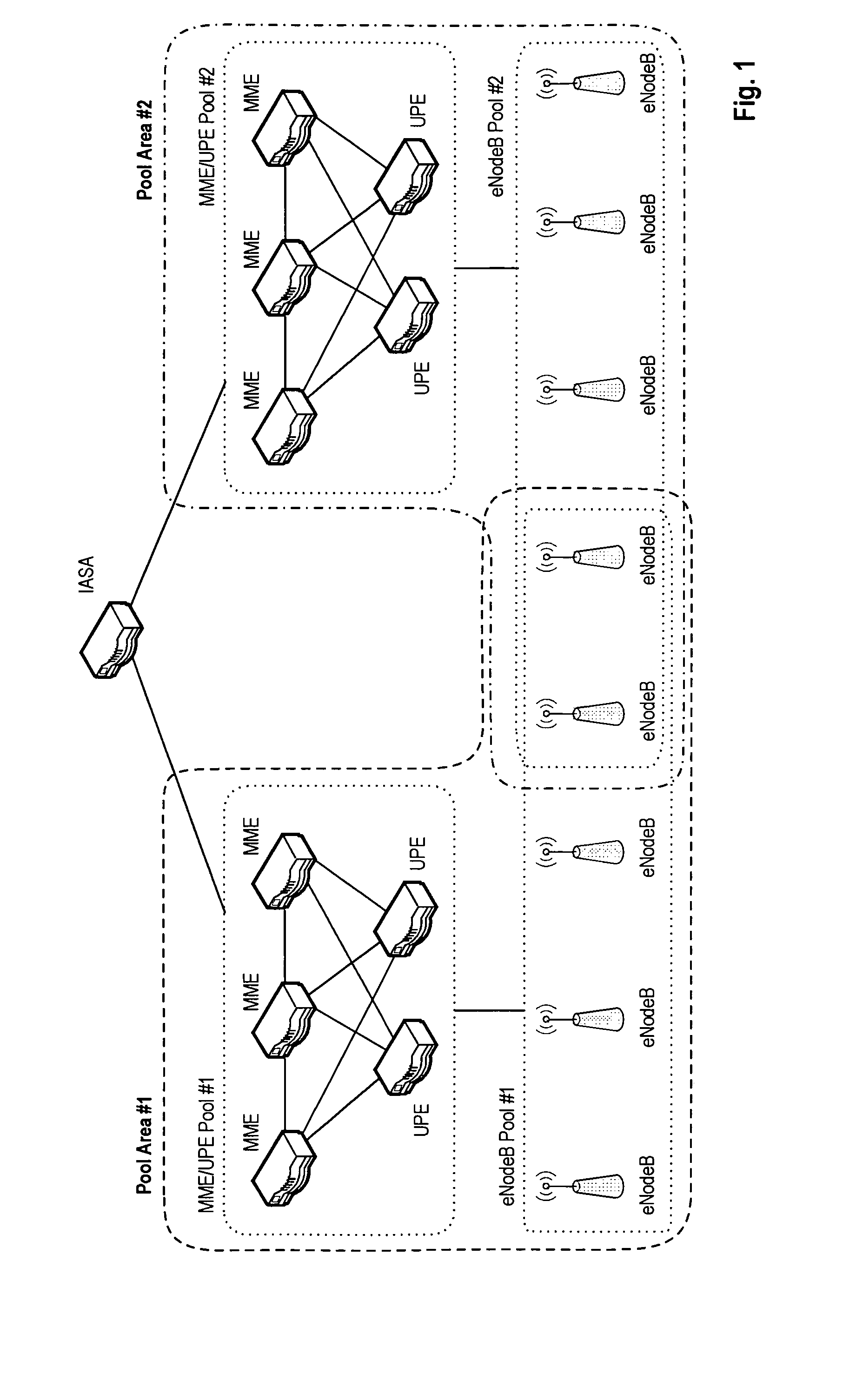
This results in establishment of a multicast user plane only to one of the pool areas avoiding duplicate user planes for the same multicast service, which would represent a waste of network resources.
So, terminating the user plane to the access node in the overlapping pool area because of terminals attached one pool area, results in loss of the multicast service for the remaining terminals attached to the other pool area.
However, when the access node (eNodeB #2) in an overlapping pool area terminates the multicast user plane, the mobile terminals attached to pool area #2, e.g. UE #2 can no longer receive the multicast service.
This may however result in an inefficient utilization of transmission network resources for distribution of the multicast service to eNodeBs #3, #4 and #5 located in the overlapping areas.
In the transmission network between the UPEs and the eNodeBs in the overlapping region of the pool areas, this results in unnecessarily increased allocation of resources.
The inefficiency of resource utilization might increase with the number of pool areas that overlap, as this might result in even further distribution trees for the same content.

Method used


Image

  • Multicast service provision in a mobile communication system having overlapping pool areas
  • Multicast service provision in a mobile communication system having overlapping pool areas
  • Multicast service provision in a mobile communication system having overlapping pool areas

Examples


Embodiment Construction

[0168]The following paragraphs will describe various embodiments of the invention. For exemplary purposes only, most of the embodiments are outlined in relation to an (evolved) UMTS communication system according to the SAE / LTE discussed in the Background Art section above. It should be noted that the invention may be advantageously used for example in connection with a mobile communication system such as the SAE / LTE communication system previously described, but the invention is not limited to its use in this particular exemplary communication network.

[0169]The explanations given in the Technical Background section above are intended to better understand the mostly SAE / LTE specific exemplary embodiments described herein and should not be understood as limiting the invention to the described specific implementations of processes and functions in the mobile communication network. Nevertheless, the improvements proposed herein may be readily applied in the architectures / systems descri...


PUM


Abstract

One aspect of the invention relates to ensuring service continuity of a multicast service received from an access node assigned to a first and a second pool area simultaneously. Another aspect of the invention relates to the establishment of a user plane between a user plane entity and different access nodes assigned to different pool areas simultaneously for multicast or broadcast services. To ensure service continuity of the multicast service, it is proposed that the MME serving the mobile terminal registers at the UPE providing the multicast user plane to the access node irrespective of the UPE being assigned to the same pool area / tracking area as the MME. To facilitate efficient resource utilization in the distribution of service data to access nodes located in a overlapping region of pool areas, the invention further suggests proactive and reactive schemes for ensuring the selection of a common UPE for overlapping pool areas thereby ignoring consider pool area boundaries.

Description

FIELD OF THE INVENTION[0001]One aspect of the invention relates to the establishment of a user plane between a user plane entity and different access nodes assigned to different pool areas simultaneously for multicast or broadcast service provision.[0002]Another aspect of the invention relates to a method for ensuring service continuity of a multicast service received by a mobile terminal from an access node, wherein the access node is assigned to a first and at least a second pool area simultaneously. Further, the invention relates to the different entities of a communication network, such as a mobile terminal, a mobility management entity, a user plane entity and an access node.TECHNICAL BACKGROUND[0003]For mobile communications systems it is generally required that a mobile terminal first attaches to / registers with the network before being able to receive desired services. This attachment / registration usually comprises authentication and authorization of the mobile terminal in th...

Claims


Application Information

Patent Timeline
IPC IPC(8): H04H20/71
CPCH04L12/189H04W4/08H04W8/186H04W40/02H04L67/14H04W72/005H04W76/022H04W80/04H04W60/00H04W76/12Y02D30/70H04W72/30
Inventor BECKER, RALFGONSA, OSVALDO
Owner SOVEREIGN PEAK VENTURES LLC
Learn More