
Drainage system used in cities, towns and communities

A drainage system and community technology, applied in the waterway system, sewer system, and sewage discharge, etc., can solve the problems of high cost of the pipe network of the diversion drainage system, prominent rainwater runoff pollution, and large impact on the operation of the sewage plant, etc., to reduce the late stage The effect of reducing operation and maintenance costs, construction investment and maintenance management costs, and reducing the number of pipeline crossings

Active Publication Date: 2010-03-10
CHONGQING UNIV
View PDF0 Cites 21 Cited by
  • Summary
  • Abstract
  • Description
  • Claims
  • Application Information

AI Technical Summary

Problems solved by technology

[0007] In order to overcome the serious pollution of the combined overflow water in the above-mentioned intercepting combined drainage system and the great impact on the operation of the sewage plant, the high cost of the pipeline network of the separated drainage system, the large underground space occupation, the large impact on traffic during maintenance, and the prominent initial rainwater runoff pollution , and the problems of building overflow water storage tanks and initial rain runoff storage tanks are expensive and occupy valuable urban land. Based on the idea of ​​intercepting small flow initial ground runoff on the same line, the present invention proposes a double-layer rain-sewage composite drainage inspection Drainage systems for towns and communities based on wells or further combined with the same line split double-deck drainage pipes and canals

Method used


Image

  • Drainage system used in cities, towns and communities
  • Drainage system used in cities, towns and communities
  • Drainage system used in cities, towns and communities

Examples


Embodiment 1

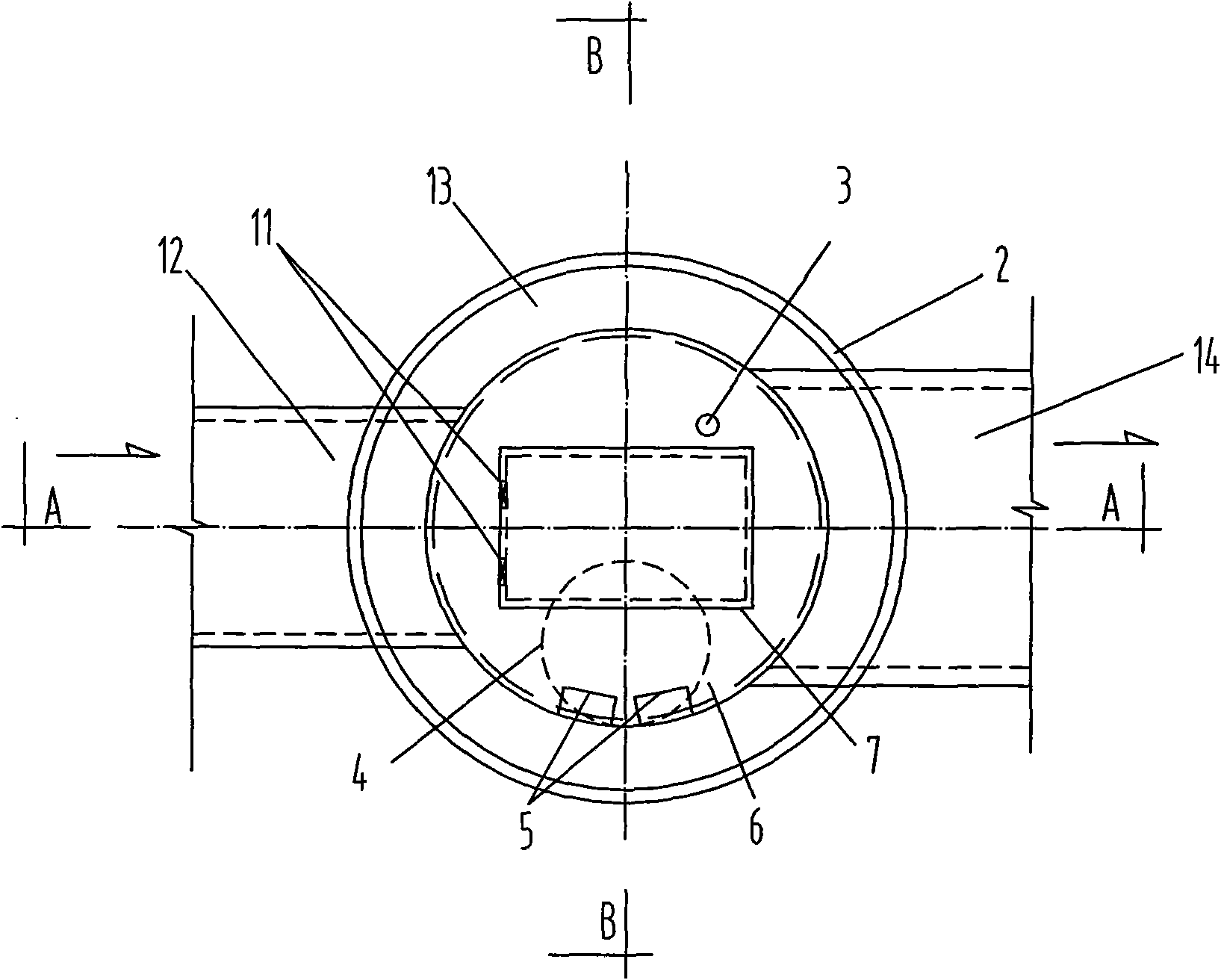
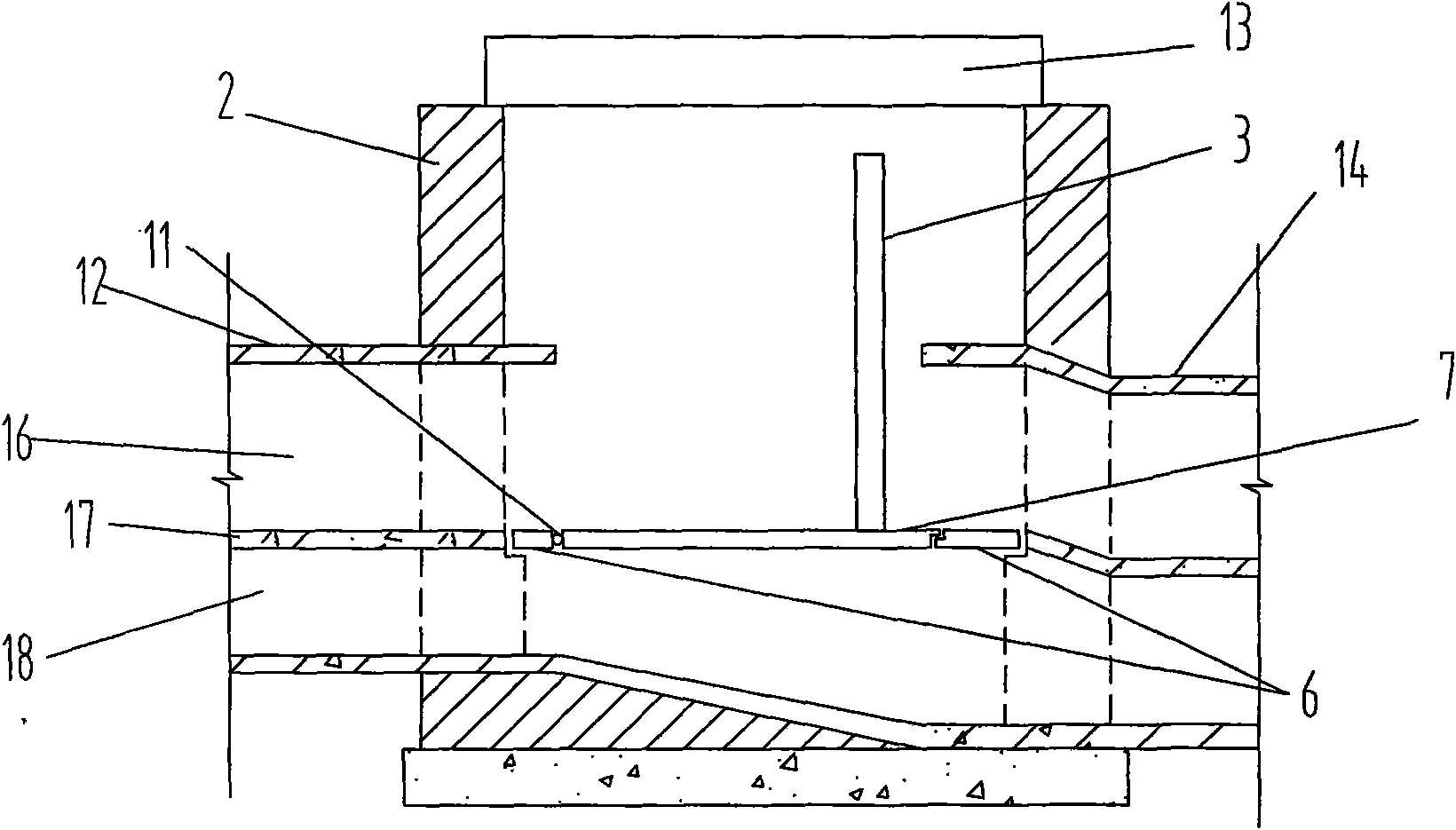
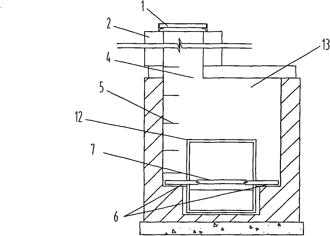
[0043] Example 1, see figure 1 , figure 2 as well as image 3 :

[0044] In the figure, this is a non-interception type co-line diversion double-layer drainage system, which is mainly composed of upstream and downstream drainage pipes 12, 14 and a rain-sewage composite double-layer drainage inspection well 13. The rain-sewage composite double-layer drainage inspection well is mainly composed of Manhole cover 1, well body 2, ventilation pipe 3, well neck 4, people's ladder 5, intermediate movable interlayer 6, movable opening and closing cover plate 7, etc. constitute. The well body 2 can be designed as a circle or a rectangle as required, and an openable and closable intermediate movable interlayer 6 is provided in the well body, which divides the inspection well into upper and lower layers, wherein the lower layer is connected to the sewage pipes and canals, and the upper layer is connected to the rainwater pipes and canals. A ventilation pipe 3 is provided to connect the...

Embodiment 2

[0047] Example 2, see Figure 4 , Figure 5 as well as Figure 6 :

[0048] This is an interception-type same-line diversion-type double-layer drainage system, which is mainly composed of upstream and downstream drainage pipes 12, 14 and a rain-sewage composite double-layer drainage inspection well 13. The rain-sewage composite double-layer drainage inspection well is mainly composed of a manhole cover 1, a well Body 2, ventilation pipe 3, well neck 4, people's ladder 5, middle movable interlayer 6, movable part 7 of middle movable interlayer, damming hole (seam) 8 etc. are formed. Different from the structure of Example 1, there is an interception hole / slot 8 on the middle movable interlayer 6, which is a circular or strip-shaped hole / slot with a fixed opening size, allowing small-flow rainfall runoff or road irrigation runoff By intercepting the water to the lower layer and connecting it to the sewage pipe, an intercepting double-layer rain-sewage composite drainage inspe...

Embodiment 3

[0049] Example 3, see Figure 7 , Figure 8 as well as Figure 9 :

[0050] This is an interception type co-line diversion type double-layer drainage system, which is mainly composed of upstream and downstream drainage pipes 12, 14 and a rain-sewage composite double-layer drainage inspection well 13. The rain-sewage composite double-layer drainage inspection well is mainly composed of manhole cover 1, Well body 2, ventilation pipe 3, well neck 4, man ladder 5, intermediate movable interlayer 6, movable opening and closing cover plate 7, closure hole / slit 8, closure hole cover plate 9, spring 10, and loose leaf 11. Different from the structure of Example 1, the intercepting structure provided on the middle movable interlayer 6 is adjustable, and the intercepting structure is specifically composed of an intercepting hole / slot 8, an intercepting hole cover plate 9, a spring 10, and a hinge 11. Composition, the interception hole cover plate 9 is installed on the interception ho...


PUM


Abstract

The invention requests to protect a drainage system used in cities, towns and communities, which is formed by connecting at least a co-line divided-flow dual-layer drainage pipe and channel or a common drainage pipe and channel with a rainwater-sewage compound dual-layer manhole. An intercepting rainwater-sewage compound dual-layer drainage manhole can be arranged on the drainage system accordingto the requirement so as to realize that the initial surface runoff is intercepted into a sewage pipe and channel and is delivered to a sewage treatment plant to be treated, and a non-intercepting rainwater-sewage compound dual-layer drainage manhole can be arranged according to the requirements of direction change, gradient change, connector change, pipe and channel intersection, examination andrepair of linear pipes and channels every certain distance and other special purposes. The drainage system can realize individual delivery and drainage of the rainwater and sewage by layers on the same pipeline and has the characteristics of simple pipelines, few manholes, low investment, operation and maintenance cost, capability of reducing the pollution effects of first rain runoff in an economic and effective manner, and no rainwater-sewage interflow and overflow water pollution, etc.

Description

technical field [0001] The invention belongs to the technical fields of urban drainage systems and environmental protection, and in particular relates to a drainage system. Background technique [0002] At present, there are mainly two systems in the field of urban drainage: the confluence system and the diversion system. The former is to transport and discharge rainwater and urban sewage in the same pipeline, and the latter is to transport rainwater and urban sewage separately in two pipeline systems. and emissions. At present, they all have certain defects and deficiencies respectively. [0003] For the intercepting combined drainage system, the main problems are: (1) There is rain-sewage combined overflow water in the rainy season, which contains a large amount of organic matter, suspended solids (SS) and pathogenic microorganisms, and is directly discharged into the water body without treatment. The pollution effect is large; (2) When the drainage pipeline is far away ...

Claims


Application Information

Patent Timeline
IPC IPC(8): E03F1/00E03F3/02E03F5/02
Inventor 姜文超周健何强龙腾锐吕念南杨政成饶碧华
Owner CHONGQING UNIV
Learn More