Structure of exhaust section of gas turbine and gas turbine

a technology of gas turbine and exhaust section, which is applied in the direction of machines/engines, stators, liquid fuel engines, etc., can solve the problems of less resistance of instruments disposed around bearings to high temperature and the effect of reducing the efficiency of gas turbin

Active Publication Date: 2010-12-23
MITSUBISHI POWER LTD
View PDF13 Cites 97 Cited by
  • Summary
  • Abstract
  • Description
  • Claims
  • Application Information

AI Technical Summary

Benefits of technology

[0025]The structure of the gas turbine according to the first aspect of the present invention and the gas turbine according to the second aspect are advantageous in that the pressure difference between the outside of the casing and the inside of the gas path part causes air to flow from the outside of the casing along the strut to cool the strut, and therefore, the strut and the periphery of the bearing can be cooled without decreasing the efficiency of the gas turbine and without being affected by load variations.

Problems solved by technology

However, since the air used for cooling is extracted from the compressor section, the techniques have a problem that the efficiency of the gas turbine decreases accordingly.
In general, the instruments disposed around the bearing are less resistant to high temperature and thus can be damaged by the air heated to about 400° C. or higher as described above.

Method used


Image

  • Structure of exhaust section of gas turbine and gas turbine
  • Structure of exhaust section of gas turbine and gas turbine
  • Structure of exhaust section of gas turbine and gas turbine

Examples


Embodiment Construction

[0031]A gas turbine according to an embodiment of the present invention will be described with reference to FIGS. 1 to 5.

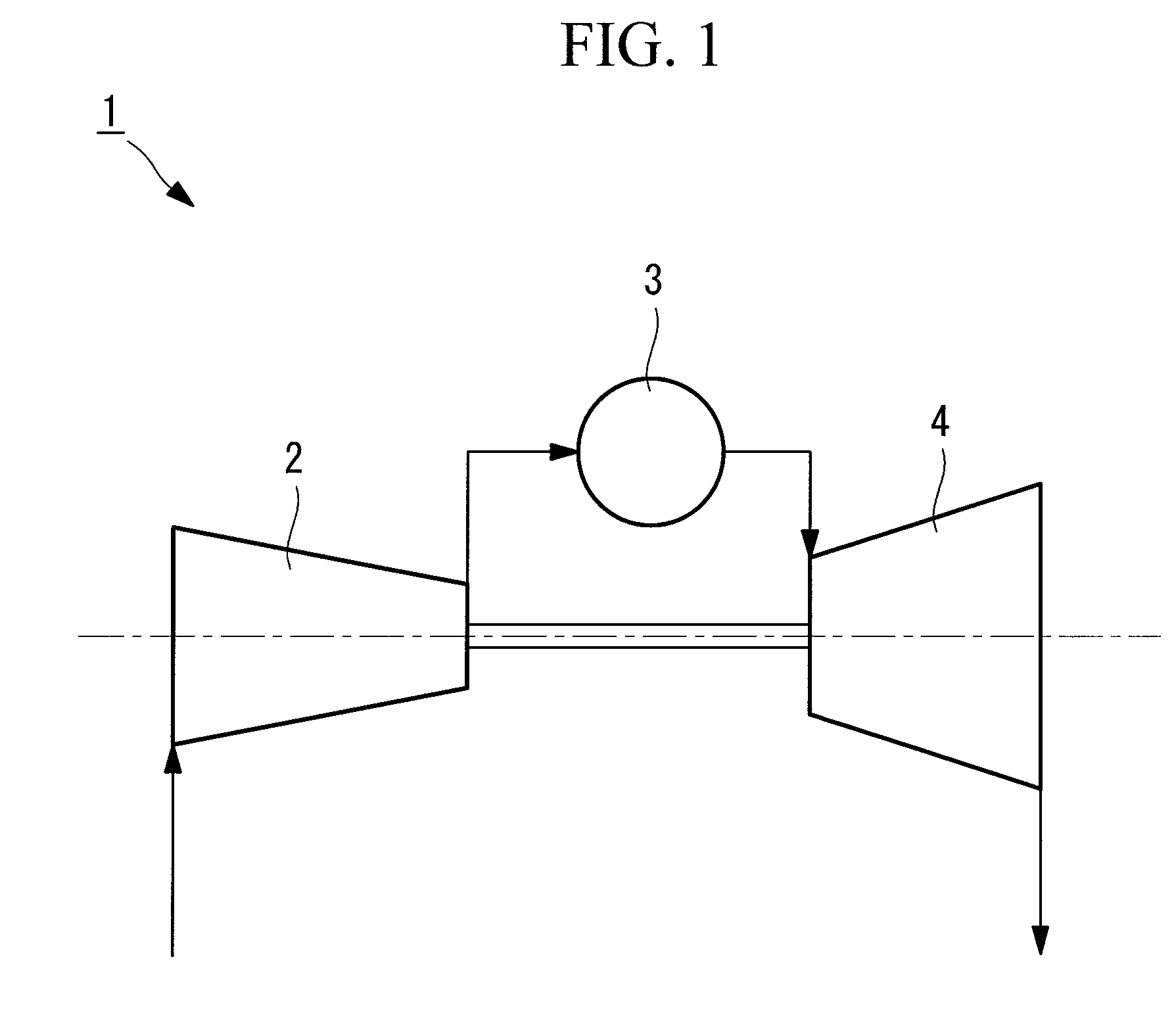
[0032]FIG. 1 is a schematic diagram illustrating a configuration of a gas turbine according to this embodiment.

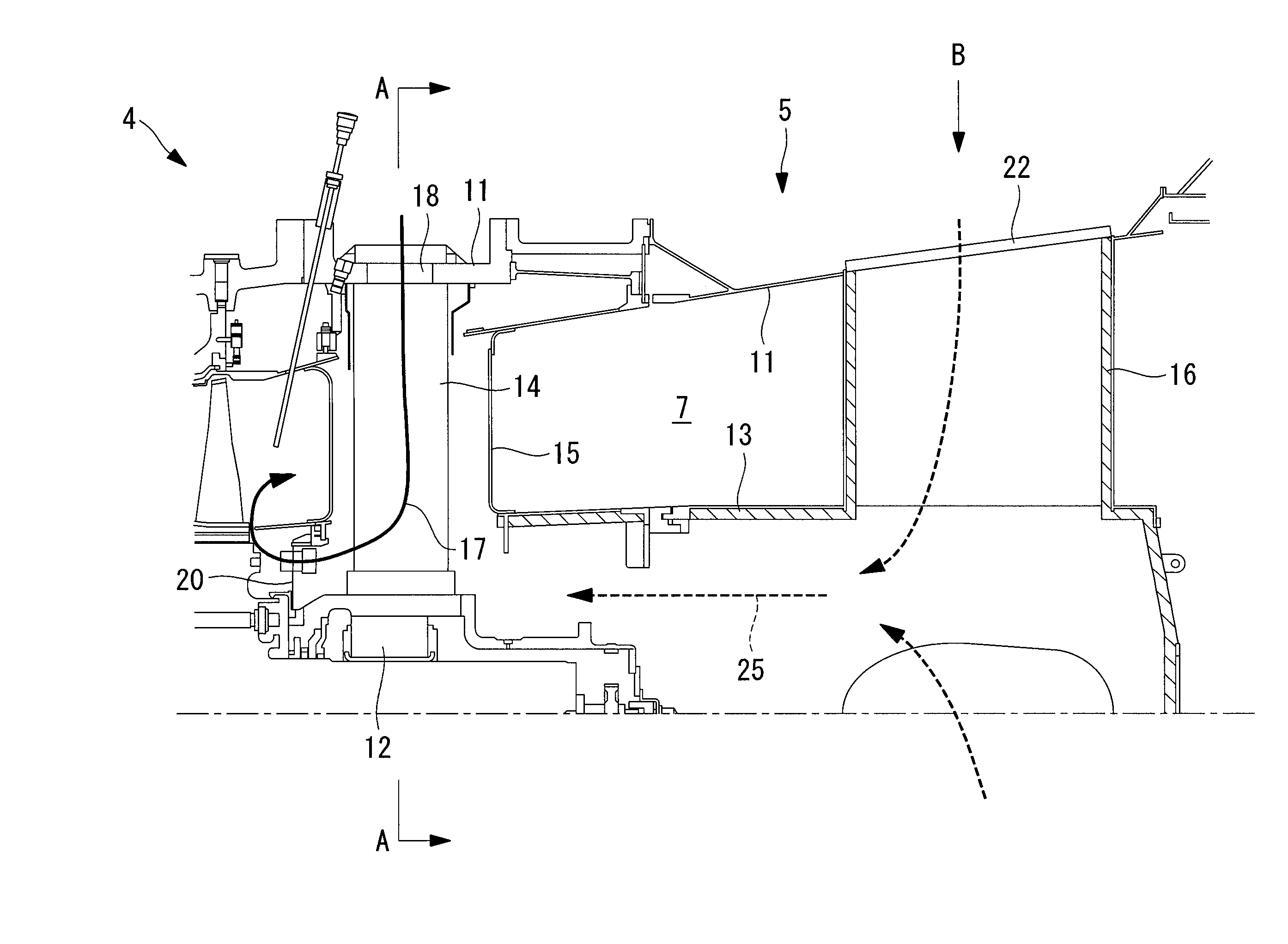
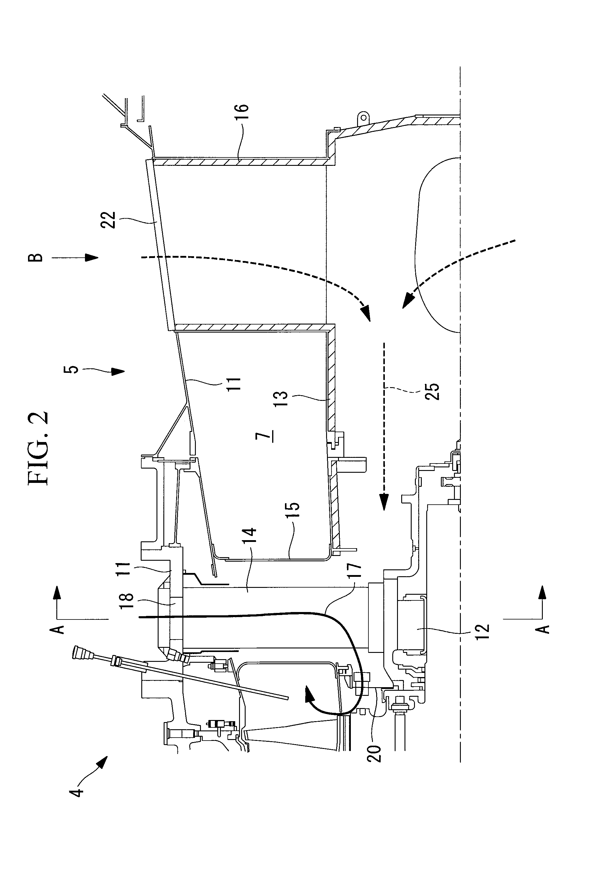
[0033]As shown in FIG. 1, a gas turbine 1 according to this embodiment has a compressor section 2 that compresses air, a combustor 3 that mixes the compressed air and fuel to cause combustion to generate combustion gas, a turbine section 4 that derives rotational driving force from the combustion gas, and an exhaust section 5 that receives exhaust gas discharged from the turbine section 4.

[0034]The compressor section 2 compresses intake air and supplies the compressed air to the combustor 3.

[0035]The compressor section 2 and the turbine section 4 are installed on a rotary shaft 6, and the turbine section 4 rotationally drives the compressor section 2.

[0036]The combustor 3 mixes the compressed air supplied from the compressor section 2 with fuel to cause c...


PUM


Abstract

There is provided an exhaust section of a gas turbine and a gas turbine that can cool a strut and the periphery of a bearing without decreasing the efficiency of the gas turbine. A structure of an exhaust section of a gas turbine has: a casing in which a gas path part is formed; a bearing part that rotatably supports moving blades of a turbine section; a strut that extends inwardly from the casing and supports the bearing part; an opening formed in the casing; and a cooling flow channel that extends from the opening toward the bearing part along the strut to guide air at a lower temperature than an exhaust gas flowing in the gas path part to the gas path part and opens into the gas path part at a position downstream of a last-stage moving blade of the turbine section.

Description

RELATED APPLICATIONS[0001]The present application is national phase of PCT / JP2008 / 072327 filed Dec. 9, 2008, and claims priority from Japanese Application Number 2008-003368 filed Jan. 10, 2008, the disclosures of which are hereby incorporated by reference herein in their entirety.TECHNICAL FIELD[0002]The present invention relates to a structure of an exhaust section of a gas turbine and to a gas turbine.BACKGROUND ART[0003]In general, an exhaust chamber of a gas turbine has a diffuser that efficiently recovers the pressure of the high-temperature gas exhausted from the turbine, a bearing that rotatably supports a rotor, a strut that supports the bearing to a casing or the like, and other components.[0004]The gas turbine further has a vibration meter or other instruments disposed around the bearing to detect any vibration occurring during operation of the gas turbine.[0005]Recent gas turbines are improved in efficiency and discharge exhaust gas at higher temperature accordingly. Thu...

Claims


Application Information

Patent Timeline
Patent Type & Authority Applications(United States)
IPC IPC(8): F01D5/08
CPCF01D5/081F01D9/065F05D2220/3215F01D25/30F02C7/18F01D25/12
Inventor TANIOKA, TADATERU
Owner MITSUBISHI POWER LTD
Why Eureka
Try Eureka