Method of determining the position of a deep brain stimulation electrode

lectrode technology, applied in the field of determining the position of a deep brain stimulation electrode, can solve the problems of rigidity and akinesia, difficult to find the optimum physiological target, and substantial inability to postural stability and test walking, etc., to achieve efficient finding and display, easy identification, and image alignment

Active Publication Date: 2010-12-23
BRAIN & BEYONDS CO LTD +1
View PDF7 Cites 55 Cited by
  • Summary
  • Abstract
  • Description
  • Claims
  • Application Information

AI Technical Summary

Benefits of technology

[0027]According to a method of determining the position of the DBS electrode according to the present invention, the position of the DBS electrode with respect to a deep brain target region such as an STN can be clearly found. Finding the position is usefully used to design an implantation of the DBS electrode, implant the DBS electrode and evaluate the implantation of the DBS electrode.
[0028]Also, according to a method of determining the position of the DBS electrode, a deep brain target region can be easily identified and identification disturbance of the deep brain target region caused by the electrode can be overcome, by getting hold of the position relation between the deep brain target region and the electrode by means of image alignment between a pre-implantation volume data set and a post-implantation volume data set.
[0029]Also, according to a method of determining the position of the DBS electrode, the position relation...

Problems solved by technology

To find an optimum physiological target is very difficult in a DBS implantation for treating a movement disorder, particularly, in the treatment of symptoms that cannot be tested on an operating table during an implantation of an electrode lead.
For example, in the case of a patient having the Parkinson's disease, postural stability and test walking are substantially impossible during an implantation of a DBS lead.
It is also known that rigidity and akinesia, which are two other major symptoms of the Parkinson's disease, are difficult to quantitatively evaluate during an ...

Method used


Image

  • Method of determining the position of a deep brain stimulation electrode
  • Method of determining the position of a deep brain stimulation electrode
  • Method of determining the position of a deep brain stimulation electrode

Examples


Embodiment Construction

[0042]Hereinafter, the present invention will be described in detail with reference to the accompanying drawings.

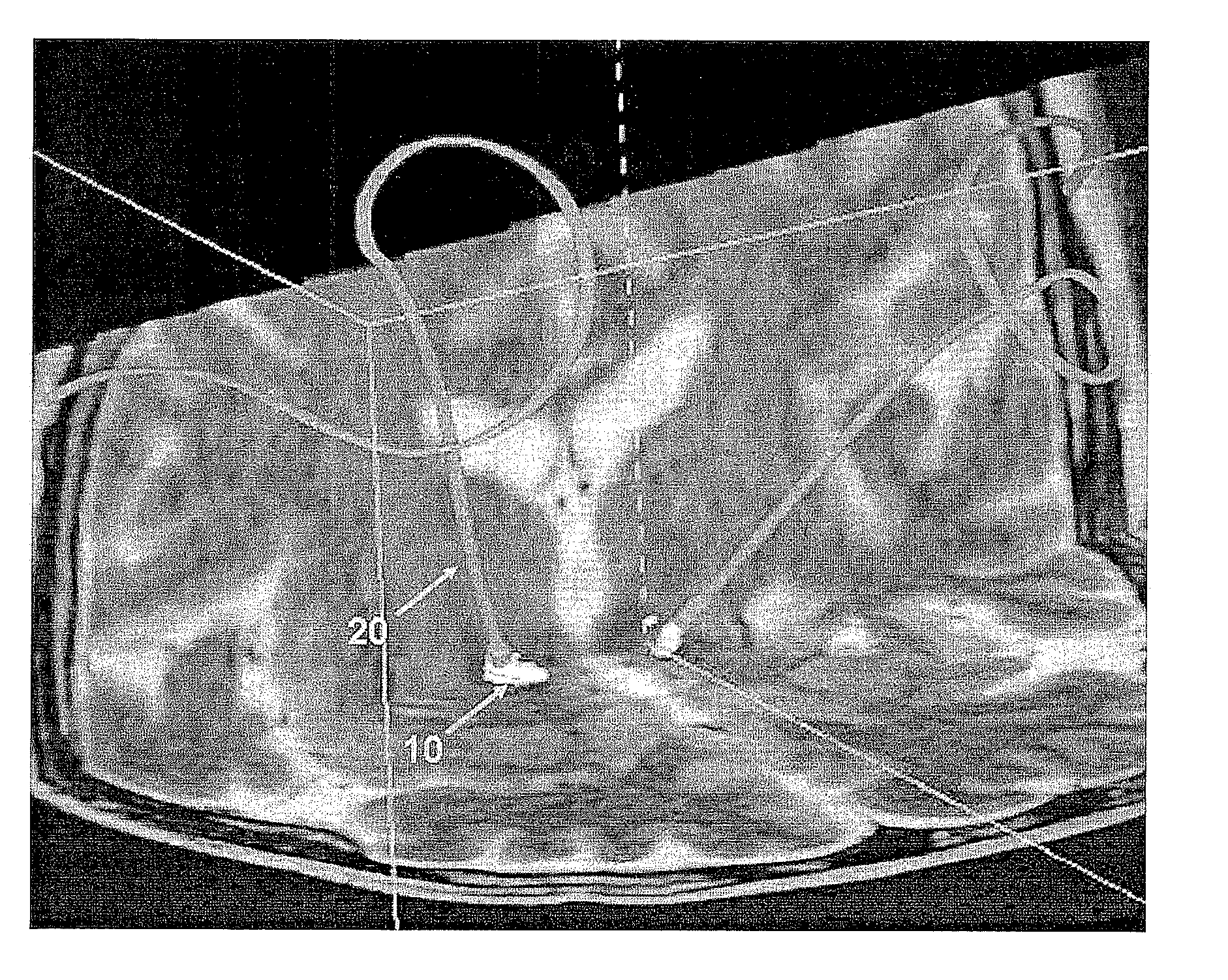
[0043]FIG. 3 is an explanatory view illustrating a method of evaluating the position relation between a target region and a DBS electrode according to the present invention. A DBS electrode 20 is positioned on a subthalamic nucleus (STN) 10.

[0044]FIG. 4 is an enlarged view of FIG. 3. Three exposed DBS electrodes 12, 13 and 14 are shown on a right-side STN 10. Therefore, a doctor can be informed that one of the four DBS electrodes exists within the STN 10. Since the doctor precisely knows the position of the DBS electrode with respect to the STN 10, he or she can clearly judge whether an implantation of the DBS electrode is successful, which DBS electrode needs electric stimulation, etc. to thereby reduce a treatment time of a patient. In addition, provided is the basis for precisely understanding the correlation between the electric stimulus and the target region, which h...


PUM


Abstract

The present invention relates to a method of determining the position of a deep brain stimulation (DBS) electrode which finds the position of the DBS electrode with respect to a deep brain target region, by using a first volume data set containing information on the deep brain target region and a second volume data set containing information on the DBS electrode implanted toward the deep brain target region, and which includes: a first step of generating a subvolume of the deep brain target region from the first volume data set, and also generating a subvolume of the DBS electrode from the second volume data set; and a second step of overlapping and displaying the subvolume of the deep brain target region and the subvolume of the DBS electrode.

Description

TECHNICAL FIELD[0001]The present invention relates to a method of determining the position of a deep brain stimulation (DBS) electrode, and more particularly, to a method of finding the position of a subvolume-rendered DBS electrode with respect to a subvolume-rendered subthalamic nucleus (STN), by aligning a pre-implantation MRI volume data set and a post-implantation CT volume data set.BACKGROUND ART[0002]A DBS therapy treats an abnormal state of a patient by fixing an electrode to an aimed target (e.g., STN) of a deep brain and continuously applying electric stimulation thereto for a predetermined period.[0003]Since firstly approved in 1998 by U.S. FDA, the DBS therapy has been very popular in the treatment of various brain-controlled disorders including a movement disorder. The DBS therapy has been applied to the treatment of drug induced side effects of patients suffering from essential tremor, rigidity, Parkinson's disease and tremor. In general, this therapy includes position...

Claims


Application Information

Patent Timeline
IPC IPC(8): A61B5/055G06T7/00A61B5/05
CPCA61B19/52A61N1/0534A61B2019/5289A61B90/36A61B2090/364A61B10/00A61N1/05
Inventor PAEK, SUN HALIM, YONG HOONKANG, HYUN JAESHIN, SE HOCHOI, EUN JUKIM, CHEOL YOUNG
Owner BRAIN & BEYONDS CO LTD
Why Eureka
Try Eureka