Transducer For Ultrasonic Diagnosis Device And Method For Manufacturing The Same

a technology of ultrasonic diagnosis and manufacturing method, which is applied in the direction of mechanical vibration separation, instruments, tomography, etc., can solve the problems of reducing efficiency and a productivity of manufacturing, complex and difficult process of inserting fpcb b>38/b> into backing block b>32/b>, etc., to improve acoustic efficiency, prevent acoustic loss and distortion, and simple configuration

Active Publication Date: 2010-12-23
SAMSUNG MEDISON
View PDF6 Cites 12 Cited by
  • Summary
  • Abstract
  • Description
  • Claims
  • Application Information

AI Technical Summary

Benefits of technology

[0027]A transducer of an ultrasonic diagnosis device and a manufacturing method thereof according to example embodiments of the present invention may omit a FPCB that is used for a prior art transducer, since electrode patterns that connects piezoelectric elements and a controller is directly formed inside a backing block, thereby forming the transducer in a simple configuration.
[0028]A transducer of an ultrasonic diagnosis device and a manufacturing method thereof according to example embodiments of the present invention may prevent acoustic loss and distortion caused by the FPCB by omitting the FPCB, and may improve an acoustic efficient by eliminating a mass effect of the FPCB. In addition, a complex process of installing the FPCB in a backing block is omitted, and thus, the transducer may be easily manufactured and a productivity of the manufacturing of the transducer may increase.
[0029]A transducer of an ultrasonic diagnosis device and a manufacturing method thereof according to example embodiments of the present invention may conveniently form electrode patterns, inside a backing block, in various forms according to a circumstance and a designing condition of the transducer, and thus, the transducer may be easily applicable to various types of probes.

Problems solved by technology

However, according to the example of the transducer 10, the terminals 18a and the piezoelectric elements 14 are soldered and connected at very small intervals by using separate signal lines 19, and thus, an efficiency and a productivity of manufacturing is reduced due to a low efficiency caused by the soldering.
However, according to the example of the transducer 30, the FPCB 38 is vertically inserted into the backing block 32, and a process of inserting the FPCB 38 into the backing block 32 is very complex and difficult.

Method used


Image

  • Transducer For Ultrasonic Diagnosis Device And Method For Manufacturing The Same
  • Transducer For Ultrasonic Diagnosis Device And Method For Manufacturing The Same
  • Transducer For Ultrasonic Diagnosis Device And Method For Manufacturing The Same

Examples


Embodiment Construction

[0042]Reference will now be made in detail to example embodiments, examples of which are illustrated in the accompanying drawings, wherein like reference numerals refer to the like elements throughout. An ultrasonic diagnosis device utilizing a touch interaction is described below to explain the present disclosure by referring to the figures.

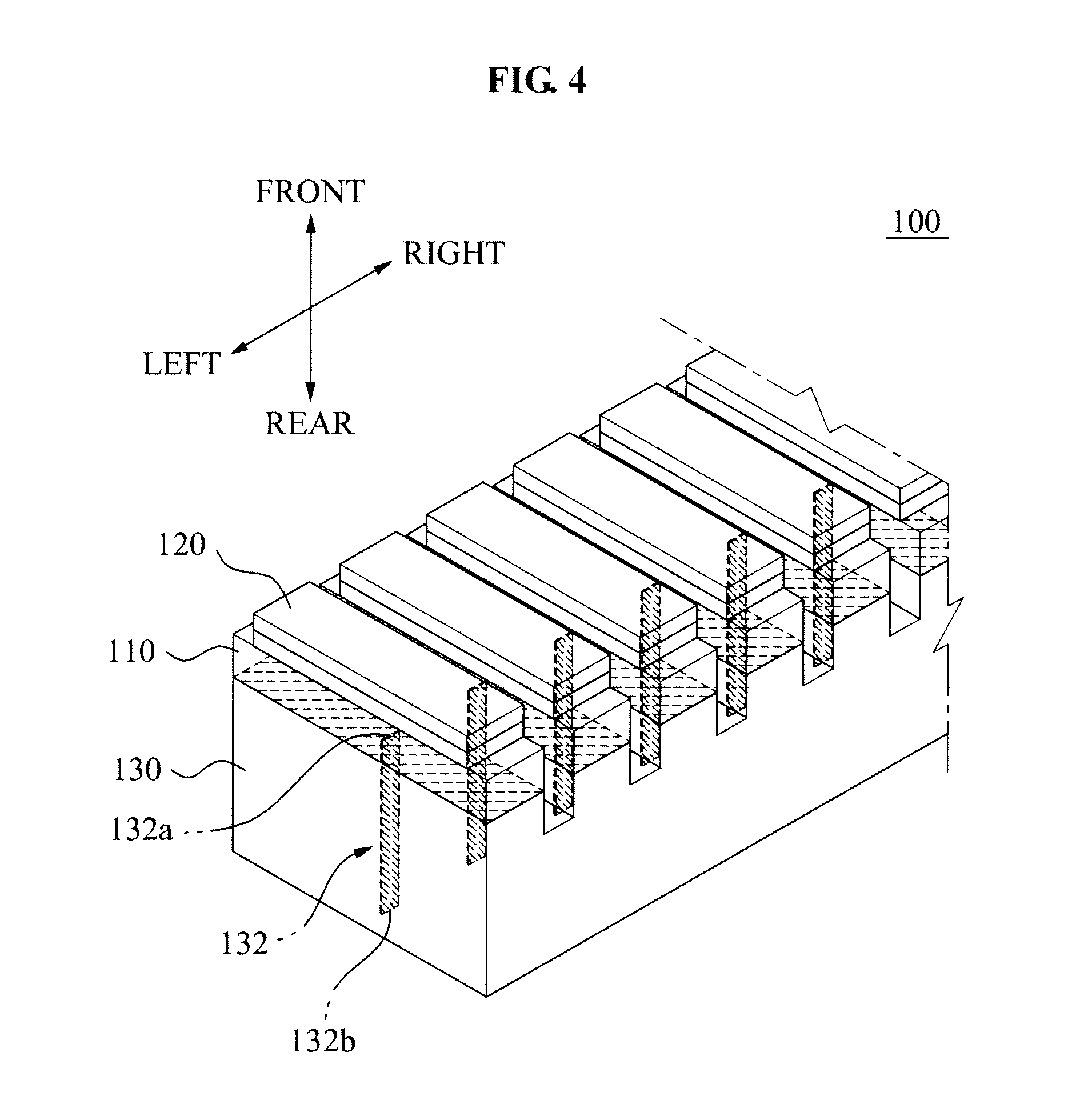
[0043]FIG. 4 is a diagram roughly illustrating main portions of a transducer of an ultrasonic diagnosis device according to an example embodiment of the present invention, FIG. 5 is a front view of the main portions of the transducer of FIG. 4, and FIG. 6 is a perspective view of a cross-section of a backing block according to the I-I line of FIG. 5.

[0044]Referring to FIG. 4, a transducer 100 of an ultrasonic diagnosis device includes piezoelectric elements 110, matching layers 120, and a backing block 130.

[0045]The piezoelectric elements 110 are elements to transmit an ultrasonic signal to a target object and to receive a returned ultrasonic si...


PUM


Abstract

Disclosed is a transducer of an ultrasonic diagnosis device. Electrode patterns are formed inside a backing block, as one body, and thus, a prior art FPCB may be omitted.

Description

CROSS-REFERENCE TO RELATED APPLICATION[0001]This application claims the benefit of Korean Patent Application No. 10-2009-0056073, filed on Jun. 23, 2009, in the Korean Intellectual Property Office, the disclosure of which is incorporated herein by reference.BACKGROUND[0002]1. Field[0003]The present invention relates to a transducer of an ultrasonic diagnosis device and a manufacturing method of the transducer, and more particularly, to a transducer of an ultrasonic diagnosis device and a manufacturing method thereof that has a simple configuration, is easy to be manufactured, and prevents a loss and a distortion of an ultrasonic signal.[0004]2. Description of the Related Art[0005]In general, an ultrasonic diagnosis device shoots a sound wave (2 MHZ to 20 MHz) that is not heard by a human, namely, an ultrasonic signal, to a target object to generate an image of an internal tissue of the target object based on a reflected ultrasonic signal from the target object. The ultrasonic has di...

Claims


Application Information

Patent Timeline
Patent Type & Authority Applications(United States)
IPC IPC(8): A61B8/14H01L41/053
CPCG10K11/004B06B1/0622A61B8/00H04R17/00H04R31/006
Inventor KIM, JIN-KISEO, JEONG-CHOL
Owner SAMSUNG MEDISON
Why Eureka
Try Eureka