Intervertebral spinal disc prosthesis

a technology for disc prosthesis and vertebrae, which is applied in the field of intervertebral disc prosthesis, can solve the problems of excessive force on the facet, drastic treatment, and inability to restore normal disc function, and achieve the effect of maintaining disc stability and integrity

Active Publication Date: 2010-12-23
MEKATRONIX
View PDF100 Cites 36 Cited by
  • Summary
  • Abstract
  • Description
  • Claims
  • Application Information

AI Technical Summary

Benefits of technology

[0024]The subject invention provides a spinal disc prosthesis capable of providing spatial movement with up to 6 degrees of freedom. Advantageously, the device of the subject invention can facilitate normal motion by allowing independent sagittal, lateral, and axial vertebral displacements and rotations when utilized in the spine of a patient.
[0025]In one embodiment, the modular spinal disc prosthesis of the subject invention comprises superior and inferior vertebral plates, that secure a replaceable six-degrees of freedom (6-DOF) modular prosthetic disc mechanism (linkage). The devices of the subject invention can achieve up to 6 degrees of freedom, including up to 3 independent rotational degrees of freedom and up to 3 independent linear degrees of freedom, such that the device of the subject invention facilitates sagittal, lateral, and axial vertebral displacements and rotations when utilized in the spine of a patient. The modular prosthetic disc mechanism of the subject invention can utilize a multi-curvate ball-and-socket type joint coupled with a central, compressible and extendible hydraulic cylinder attached orthogonally to a planar bearing for general positioning and orienting of the superior vertebra with respect to the inferior vertebra of a Functional Spinal Unit (FSU). In a particular embodiment the multi-curvate surfaces are generally spherical with a common center.
[0026]In one embodiment, the interior mechanisms of the invention kinematically connect a superior and inferior vertebral plate by means of mechanically interlocked and inseparable joint elements. The planar bearing permits sagittal and lateral displacements within the inferior vertebral plate, but cannot move in the axial direction and, thus, cannot separate from the inferior vertebral plate. The central hydraulic cylinder, which allows damped axial displacements, divides into an inferior and a superior cylinder, which are slideably fixed to each other. The inferior cylinder fixedly attaches to the plane bearing and the superior cylinder attaches fixedly to the bottom surface of the multi-curvate ball-and-socket joint. The multi-curvate “ball” interlocks with the superior vertebral plate while retaining three (3) independent degrees of rotation. Thus, all the elements remain attached to one another and the vertebral plates throughout natural FSU motion. In a further embodiment, the vertebral plates can be rigidly fixed to the superior and inferior vertebrae of a Functional Spinal Unit (FSU) or, with obvious modification of the device's vertebral plates, modularly fixed to such plates, as disclosed in U.S. Pat. No. 7,361,192 (Doty), which is hereby incorporated by reference. In a still further embodiment, displacements along the axial axis, which is used herein to refer to a line perpendicular to the axial plane of the FSU (not the patient body axial axis), arise from compressing a spring-dashpot element that also constitutes a central axial prismatic joint whose components constitute a central shock absorbing system. Hydraulic portals within the device can also provide shock absorbing characteristics, while at the same time forcing a bio-lubricant, or other substance, to flow through and around the components of the device. This axial prismatic joint, which includes a combined dual cylinder and a spring stack, provide a column element that resists shear forces and promotes the rotation and translation of the various joint elements when the FSU is subjected to shear forces.

Problems solved by technology

The latter treatment, while providing short term relief, often leads to excessive forces on facet joints adjacent to the fusion and creates further problems over time.
Drastic treatments are usually unable to restore normal disc function.
Natural spinal motions place severe requirements on the design of a prosthetic disc; simple rotational joints are not able meet those requirements.
In addition, motion coupling between axial and lateral bending and other functional spinal units involved in the overall spinal motion increases the complexity and difficulty in developing a prosthetic disc replacement that realizes natural spinal motion.
However, these designs limit motion to rotation only about the socket when the two plates are in contact.
Further, when the two plates, as described in the cited patents, are not in contact, the devices are unable to provide stability to the intervertebral interface, which can allow free motion and lead to disc related spondylolisthesis, FSU instability and excessive facet loading.
In addition, the sliding disc core devices of the Bryan et al. and SB Charité™ devices do not permit natural motion of the joint for any fixed shape of the core.
Further, the core does not mechanically link the upper and lower plates of the prosthesis and is unable to maintain the intervertebral gap throughout the range of motion.
In general, unconstrained or over-constrained relative motion between the two vertebral plates in a prosthetic disc can contribute to FSU instability over time.
Current prosthetic disc technology appears to be limited in static and dynamic load handling capability.
The rigidity of the sliding core appears to offer little energy absorption and flexibility to meet the intervertebral gap requirements during motion, and may likely generate excessive reaction forces on the spine during flexion, forces that can potentially produce extra stress on facet joints and effect mobility.
This arrangement, during normal FSU operation, places moments of force on the spring that tend to distort the spring and place high stresses on the set screws holding the spring down.
As taught in these patents, the motion of the upper plate is limited to compression and rotation.
Lateral and sagittal translations are not accommodated and so general motion in the FSU is not enabled by the device.
The titanium bellows can accommodate some axial rotations, but do not seem suitable for other rotations, which can cause excessive stresses on the bellows.
But, lateral and sagittal translations and general rotations appear to be problematic in these designs.
The ability of such springs to tolerate off-axis compression forces may also be problematic.
However, this latter design does not appear to accommodate for static and dynamic loading and there appears to be no accommodation for lateral and sagittal translations.
This device has the limitations of motion similar to the Aebi device and the further limitation of not kinematically linking the two plates together with the crossbar.
There is no control on the forces involved, so this method could lead to possible stress on other spinal joints.
The variable curvatures result, typically, in line-contact bearing manifolds that will wear the surfaces, possibly causing changes in the performance and characteristic motion of the device.
This workspace varies from one FSU to another on the spine, creating considerable spinal disc prosthesis design problems.

Method used


Image

  • Intervertebral spinal disc prosthesis
  • Intervertebral spinal disc prosthesis
  • Intervertebral spinal disc prosthesis

Examples


Embodiment Construction

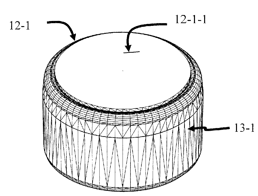
[0070]The subject invention provides embodiments of intervertebral disk prostheses. More specifically, the subject invention pertains to one or more embodiments of an intervertebral disk prosthesis capable of providing up to 6 degrees of freedom.

[0071]The subject invention is particularly useful for the treatment of spinal disk herniation. However, a person with skill in the art will be able to recognize numerous other uses, medical or otherwise, that would be applicable to the devices and methods of the subject invention. Thus, while the subject application describes a use for treatment and / or removal of spinal disk herniation, other modifications apparent to a person with skill in the art and having benefit of the subject disclosure are contemplated to be within the scope of the present invention. As used in the subject application, “kinematic chain”, “kinematic linkage”, and “kinematic connection” refer to a mechanical linkage inseparably connecting the components of the device o...


PUM

PropertyMeasurementUnit
degrees of freedomaaaaaaaaaa
displacementaaaaaaaaaa

Abstract

The subject invention provides a modular six-degrees-of-freedom spatial mechanism for spinal disc prosthesis, with three rotational and three translational degrees-of-freedom. The prosthesis anchors to the superior and inferior vertebrae of an FSU and maintains mechanical linkage between those vertebrae for all normal motions and positions of the FSU. The prosthetic disc uses a novel, multi-curvate “ball-and-socket” joint with joint limits on all three rotational axes integrated into the design. A planar joint can further provide two, orthogonal linear degrees of freedom. Resilient spring elements, self-adjusting, in position and orientation, in conjunction with a double-layered, fiber and ring reinforced boot and toroidal belt, and a unique hydraulic damping system using dual segmented-walls can accommodate dynamic and static forces and sudden shocks on the FSU.

Description

BACKGROUND OF INVENTION[0001]Spinal disc herniation, a common ailment, often induces pain, as well as neurologically and physiologically debilitating processes for which relief becomes paramount. If conservative treatments fail, the more drastic measures of discectomies and spinal fusion may be indicated. The latter treatment, while providing short term relief, often leads to excessive forces on facet joints adjacent to the fusion and creates further problems over time. Drastic treatments are usually unable to restore normal disc function. The loss of disc function has led to a number of disc prosthesis that attempt to provide natural motion.[0002]The literature documents that the Instantaneous Axis of Rotation (IAR) during sagittal rotation of the superior vertebra with respect to the inferior vertebra of a Functional Spinal Unit (FSU) in the cervical spine moves significant distances during flexion and extension of the spine (Mameren H. van, Sanches H., Beursgens J., Drukker, J., ...

Claims


Application Information

Patent Timeline
Patent Type & Authority Applications(United States)
IPC IPC(8): A61F2/44
CPCA61F2/30965A61F2310/00748A61F2002/302A61F2002/30563A61F2002/30565A61F2002/30571A61F2002/30581A61F2002/30599A61F2002/30601A61F2002/3065A61F2002/30654A61F2002/30662A61F2002/30673A61F2002/4495A61F2002/485A61F2230/0065A61F2250/0063A61F2310/00017A61F2310/00023A61F2310/00029A61F2/4425A61F2/484
Inventor DOTY, KEITH L.
Owner MEKATRONIX
Why Eureka
Try Eureka