Method for Making Wound Stator of Automotive Generator

a technology for automotive generators and wound stators, which is applied in the direction of magnets, manufacturing tools, magnets, etc., can solve the problems of high copper loss of wound stators made by conventional winding techniques, increased overall copper loss, and inability to further enhance product performan

a technology for automotive generators and wound stators, which is applied in the direction of magnets, manufacturing tools, magnets, etc., can solve the problems of high copper loss of wound stators made by conventional winding techniques, increased overall copper loss, and inability to further enhance product performan

US20100325874A1Inactive Publication Date: 2010-12-30VICTORY INDAL

Image

  • Method for Making Wound Stator of Automotive Generator
  • Method for Making Wound Stator of Automotive Generator
  • Method for Making Wound Stator of Automotive Generator

Examples


Embodiment Construction

[0033]The characteristics, subject matter, advantages, and effects of the present invention are detailed hereinafter by reference to embodiments of the present invention and the accompanying drawings. It is understood that the drawings referred to in the following description are intended for illustrative and assisting purposes only and do not necessarily show the actual proportion and precise arrangement of the embodiments. Therefore, the proportion and arrangement shown in the drawings should not be construed as limiting or restricting the scope of the present invention.

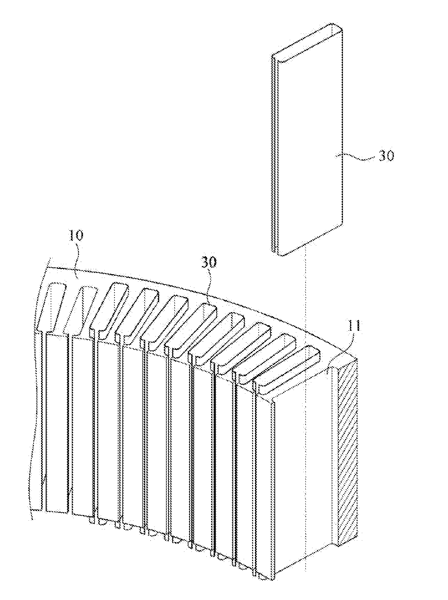
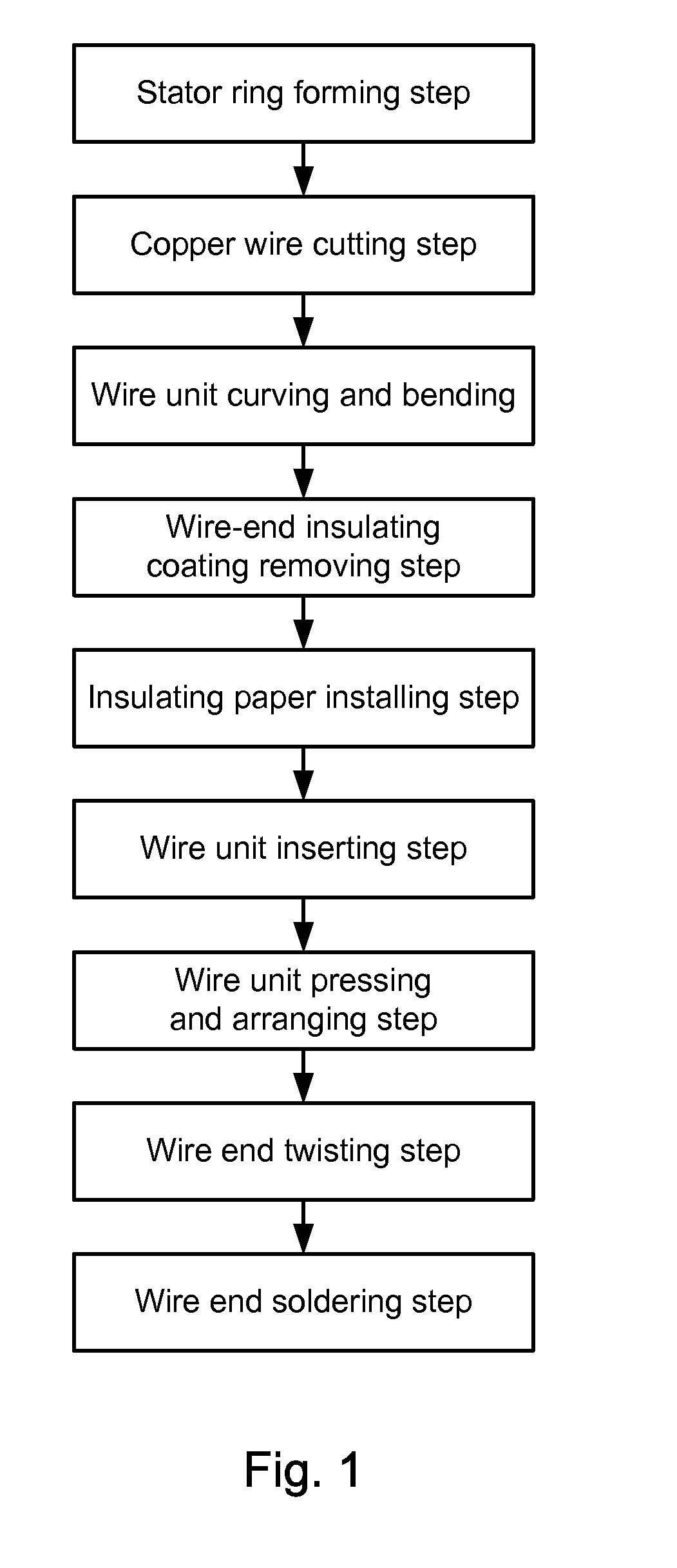
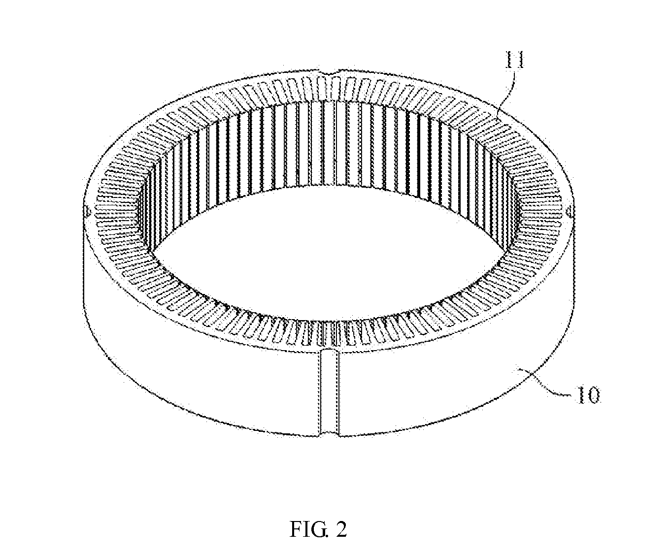
[0034]Referring to FIG. 1, a detailed method for making a wound stator of an automotive generator according to one embodiment of the present invention includes the following steps:[0035]1. Stator ring forming step,[0036]2. Copper wire cutting step,[0037]3. Wire unit curving and bending step,[0038]4. Wire-end insulating coating removing step,[0039]5. Insulating paper installing step,[0040]6. Wire unit inserting step...


PUM


Abstract

A method for making a wound stator of an automotive generator is provided for replacing the conventional winding technique. The method includes: forming a stator ring provided with a plurality of annularly arranged radial through slots; cutting a copper wire into a plurality of wire units each having a rectangular cross section; inserting the wire units into the through slots in an interlacing manner; and soldering wire ends of the wire units sequentially so as to form a connected loop.

Description

BACKGROUND[0001]1. Technical Field[0002]The present invention relates to a method for making a wound stator of an automotive generator and, more particularly, to a novel method for making a wound stator so as to enhance the power generation efficiency of a generator.[0003]2. Description of Related Art[0004]The stator is a major mechanism in an electric generator. An induced current is generated by the generator through induction between the stator and the rotor. The conventional method for making a wound stator of an automotive generator involves winding enameled wires around T-shaped claws of a stator ring so as to form a multi-layer induction coil around the stator ring.[0005]However, a wound stator made by the conventional winding technique has high copper loss. The overall copper loss is increased because the copper cores exposed from the wire ends of the enameled wire windings are rather long. Hence, not only is it impossible to further enhance product performance, but also a m...

Claims


Application Information

Patent Timeline
30 Dec 2010
Publication
US20100325874A1
IPC
H02K15/00
CPC
H02K15/0081; H02K15/064; Y10T29/49071; Y10T29/49073; Y10T29/49011; Y10T29/49009; Y10T29/53143
Inventors
WANG, CHUN-YUAN; GUAN, YU-TANG