Solar shingle system

a solar panel and roof technology, applied in the direction of photovoltaic supports, sustainable buildings, roofing, etc., can solve the problems of cumbersome conventional solar panels, unattractive additions to homes, and difficult installation, and achieve the effect of less efficient and easy installation

Inactive Publication Date: 2010-12-30
DEGENFELDER JEFFREY G +1
View PDF13 Cites 15 Cited by
  • Summary
  • Abstract
  • Description
  • Claims
  • Application Information

AI Technical Summary

Benefits of technology

[0020]In a preferred embodiment, the solar shingle of the present invention incorporates a flexible photovoltaic cell that is visible when properly installed on a roof. Two leads are connected to the photovoltaic cell, but are buried within the layers of the shingle. As shingles are overlapped on a roof, roofing nails are used to connect the shingles to the roof deck. In one embodiment, the nails act as electrical conductors that pass between the shingles and through the electrode leads. The electrodes leads are conductive layers within the shingle. The positive (+) electrode lead on a first shingle is connected to the negative (−) electrode leads on two underlying shingles. The shingle needs to be able to withstand harsh conditions. In one embodiment, the exposed PV cells are covered with a translucent material to absorb minor impacts and insulate from rain.
[0021]The system of the present invention also inc

Problems solved by technology

As previously noted, the average consumer oftentimes considers conventional solar pane

Method used


Image

  • Solar shingle system
  • Solar shingle system
  • Solar shingle system

Examples


Embodiment Construction

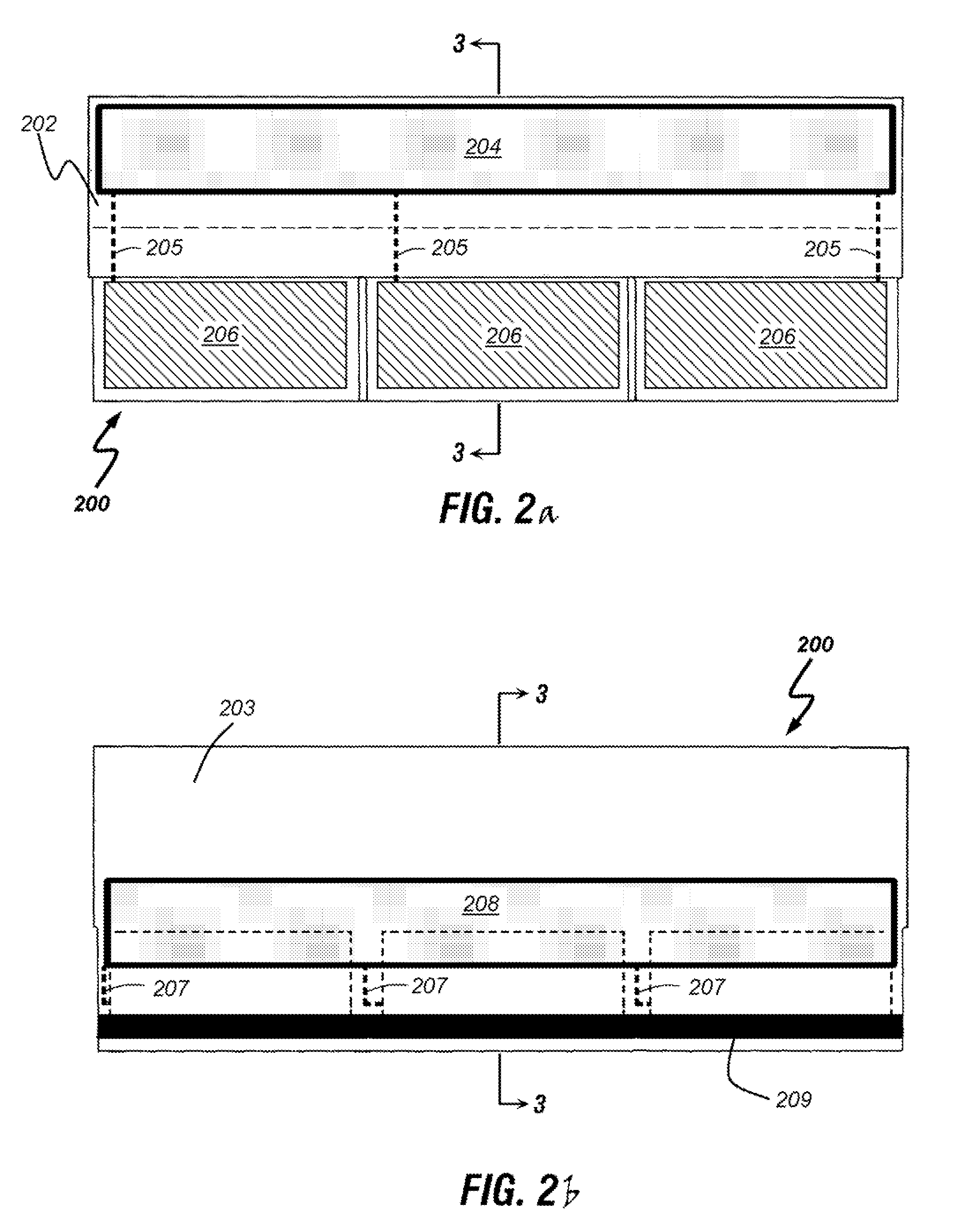
[0033]With reference to FIGS. 2a-3, an embodiment of the solar shingle of the present invention 200, which comprises a standard asphalt roofing shingle having an integrated thin film solar cell, is depicted. Asphalt shingles are typically constructed of four basic materials:

[0034]a fiberglass or cellulose backing;

[0035]asphalt cement;

[0036]sand-sized rock called aggregate; and

[0037]mineral filler or stabilizer that includes limestone, dolomite and silica.

[0038]As shown in FIG. 2a, the exterior or outer facing side 202 of each solar shingle 200 further includes a plurality of thin film solar cells 206 formed or attached thereon and electrically connected to an upper electrical connector or electrode lead 204 formed or attached to the upper portion of the exterior or outer facing side 202 of solar shingle 200. Separate electrical conduits 205, such as conductive wires, are used to electrically connect the upper electrode 204 to the plurality of thin film solar cells 206.

[0039]As shown...


PUM

PropertyMeasurementUnit
Lengthaaaaaaaaaa
Poweraaaaaaaaaa
Flexibilityaaaaaaaaaa

Abstract

The present invention comprises an asphalt roofing shingle with integrated thin film solar cells that is easy to install and scalable to each particular application. The system of the present invention comprises a standard asphalt roofing shingle manufactured with an integrated thin film solar cell connected to two electrodes configured on opposing sides of the shingle. The shingle is dimensioned to that of a standard asphalt shingle. Roofing nails, which are used to install the shingle to the roof, physically attach the shingle to the roof, may also establish an electrical connection between the electrodes of the respective shingles creating a unified electrical circuit amongst the attached solar shingles.

Description

CROSS-REFERENCE TO RELATED APPLICATION[0001]This application claims the benefit of and priority to a U.S. Provisional Patent Application No. 61 / 220,539 filed Jun. 25, 2009, the technical disclosure of which is hereby incorporated herein by reference.BACKGROUND OF THE INVENTION[0002]1. Technical Field of the Invention[0003]The present invention relates generally to photovoltaic roofing systems and more particularly to a roofing material which is capable of generating electrical power. Most specifically, the invention relates to a roofing shingle structure and wiring system which is compatible with conventional shingles and which is capable of generating electrical power.[0004]2. Description of the Related Art[0005]Environmental pollution and energy shortages are now of global concern. More interest is focusing on solar energy, which promises an unlimited source of clean energy. Solar energy is the clean and affordable solution to growing energy needs. Solar energy is a renewable ener...

Claims


Application Information

Patent Timeline
IPC IPC(8): E04D13/18E04D1/10
CPCE04D1/20E04D1/30H02S20/23Y02E10/50H01L31/02008Y02B10/12Y02B10/10
Inventor DEGENFELDER, JEFFREY G.CARSTENS, DAVID W.
Owner DEGENFELDER JEFFREY G
Why Eureka
Try Eureka