Method for producing pigment nanoparticles by forced ultrathin film rotary reaction method, pigment nanoparticles, and inkjet ink using the same

a technology of rotary reaction and pigment nanoparticles, which is applied in the direction of porphines/azaporphines, rotary stirring mixers, transportation and packaging, etc., can solve the problem of substantial inability to reduce the minute space between the processing surfaces to 10 m or less

Active Publication Date: 2010-12-30
M TECH CO LTD
View PDF6 Cites 25 Cited by
  • Summary
  • Abstract
  • Description
  • Claims
  • Application Information

AI Technical Summary

Benefits of technology

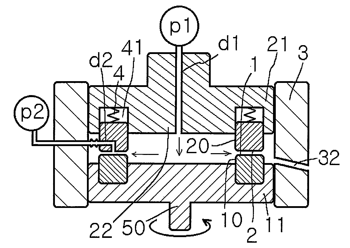
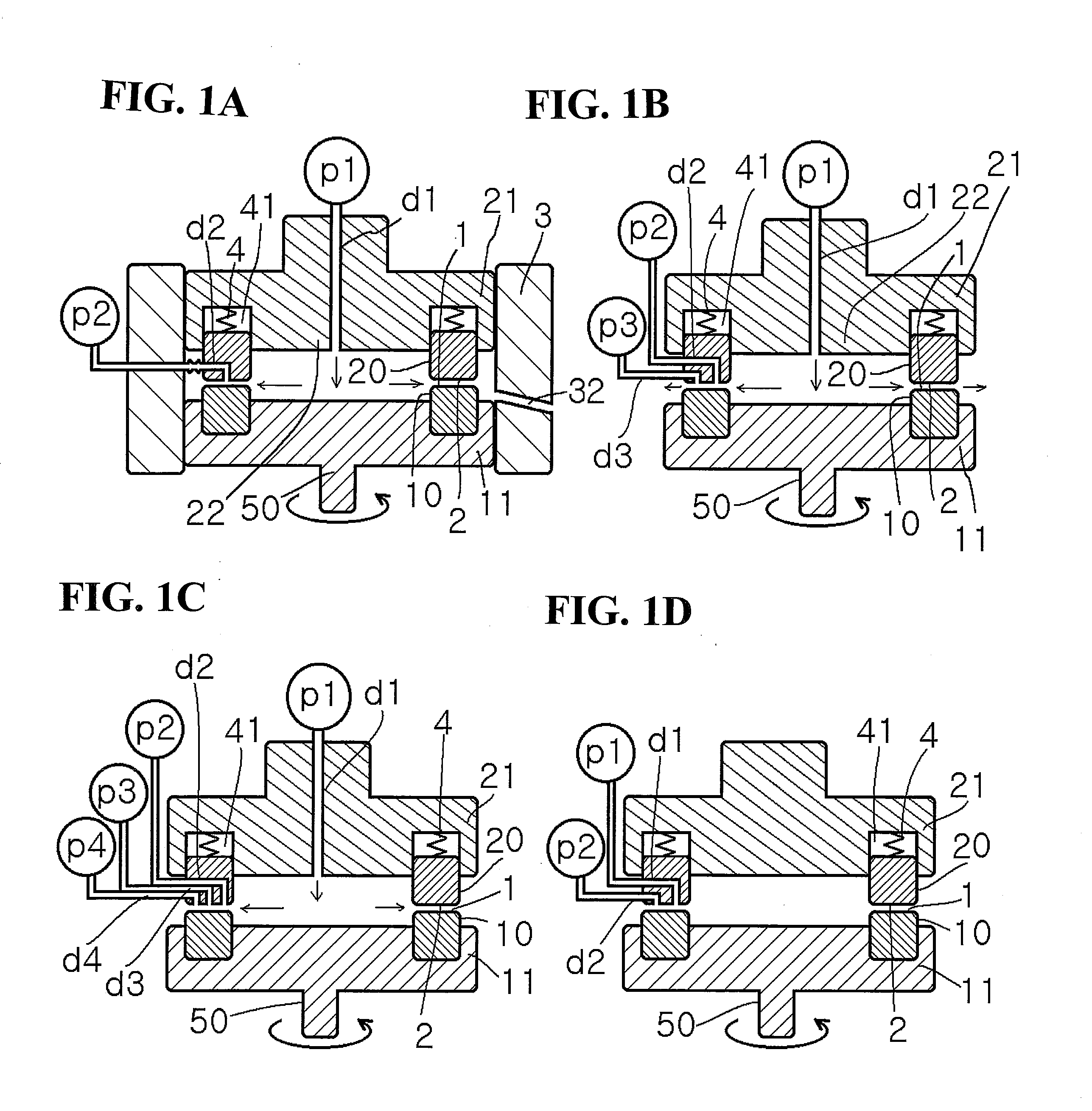
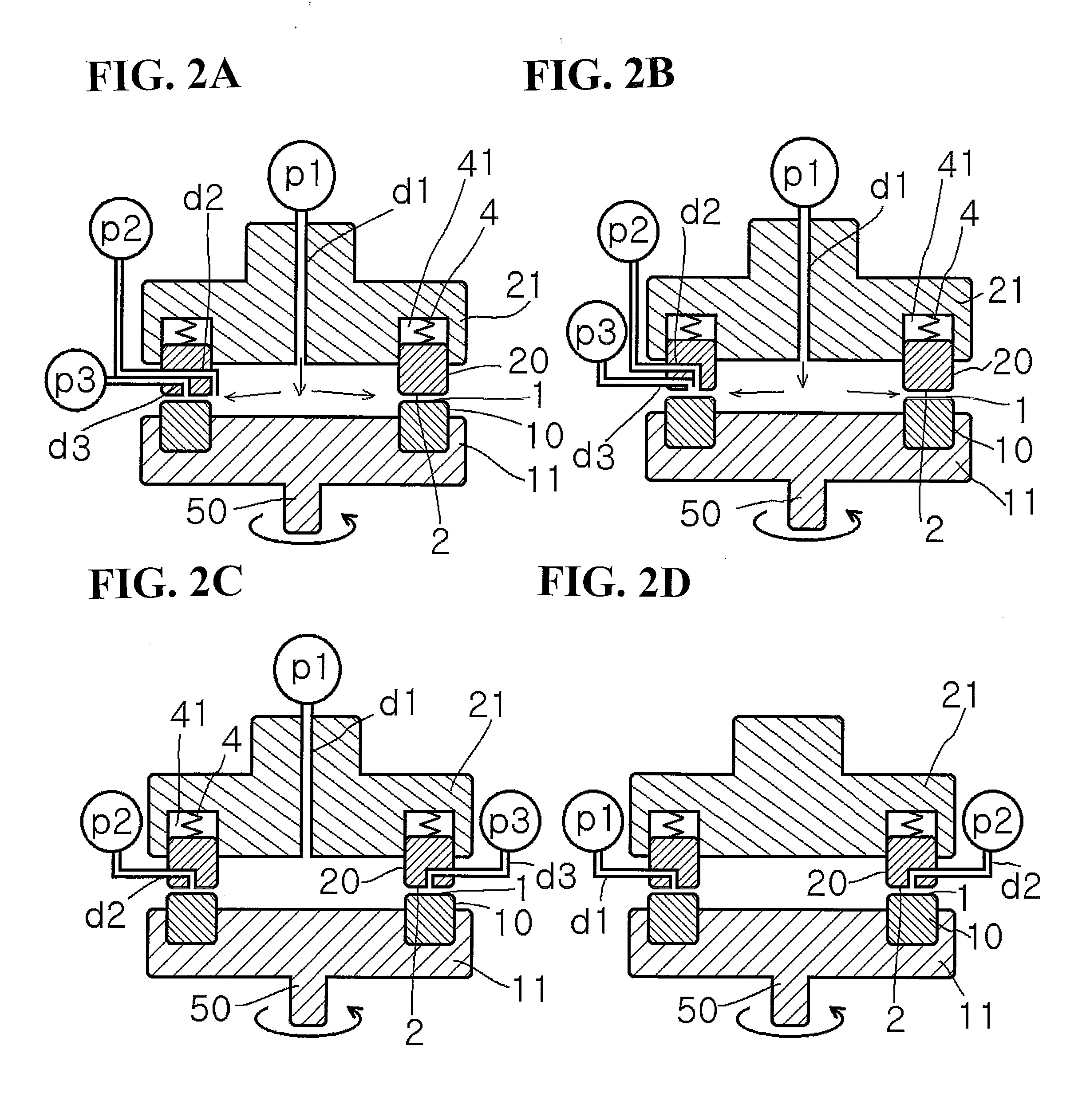
[0024]An aspect of the invention defined in claim 3 in this application provides a method for producing pigment nanoparticles, which comprises feeding a fluid to be processed between processing surfaces being capable of approaching to and separating from each other and being displaced relatively, maintaining a distance between the processing surfaces to be a minute space by the balance in pressure between a force in the approaching direction and a force in the separating direction including a supply pressure of the fluid and a pressure exerted between the rotating processing surfaces, allowing the minute space maintained between the two processing surfaces to serve as a flow path of the fluid to be processed thereby forming a forced thin film of the processed fluid, and separating pigment substances in the forced thin film.
[0035]The following effects can be obtained by allowing the respective fluids to join together in a thin-film fluid formed between the processing surfaces arranged to be opposite so as to able to approach to and separate from each other, at lest one of which rotates relative to the other thereby separating pigment nanoparticles in the thin-film fluid by the forced ultrathin film rotary reaction method.
[0036]In the above production method, stirring conditions in the minute flow path between the processing surfaces can be changed freely so that the fluid in the minute reaction flow path between the processing surfaces can be instantaneously stirred and mixed to promote the reaction. In addition, the Reynolds number of the fluid in the minute flow path can be freely changed so that pigment nanoparticles which are monodisperse and excellent in re-dispersibility, having an objective particle size, particle shape and crystal form, can be prepared. Because of the self-dischargeability of the pigment monoparticles, the flow path is not clogged with the product, and high pressure is not necessary for flowing the reaction solution, even in the reaction accompanied by separation. Accordingly, pigment nanoparticles can be stably prepared. Moreover, the pigment nanoparticles are characterized by being excellent in safety, being free of contamination with impurities derived from a production apparatus and a method such as those represented by a bead mill method, and being superior in an ability to be cleaned off. Depending on a desired amount of the product, the method can be scaled up by increasing the size of the reactor to provide a method for producing pigment nanoparticles with high productivity.
[0038]In the minute flow path between the relatively displaced processing surfaces opposite to each other in the forced ultrathin film rotary reaction method, the distance between the processing surfaces can be strictly fixed thereby giving desired reaction states, and the reaction can be carried out in the minute reaction flow path having a fixed flow path width, thus making the reaction ideal not only from the viewpoint of the rapid mixing and reaction due to molecular diffusion in the minute flow path but also from the viewpoint of concentration gradient as a parameter in chemical reaction, thereby achieving uniform heat generation accompanying the neutralization reaction by acid-alkali and re-crystallization of the pigment, so that the crystal form and particle size of the pigment can be regulated efficiently with higher accuracy.

Problems solved by technology

Methods prior to the method based on the above principle are those that involve mechanically regulating the distance between the processing surfaces and cannot absorb heat generated by rotation and its accompanying deformation or run-out, thus making substantially impossible to reduce the minute space between the processing surfaces to 10 μm or less.

Method used


Image

  • Method for producing pigment nanoparticles by forced ultrathin film rotary reaction method, pigment nanoparticles, and inkjet ink using the same
  • Method for producing pigment nanoparticles by forced ultrathin film rotary reaction method, pigment nanoparticles, and inkjet ink using the same
  • Method for producing pigment nanoparticles by forced ultrathin film rotary reaction method, pigment nanoparticles, and inkjet ink using the same

Examples


example 1

[0440]While an aqueous solution of Disperbyk-184 (manufactured by BYK-Chemie) was sent as a first fluid from the center at a supply pressure / back pressure of 0.02 MPa / 0.01 MPa, at a revolution number of 1000 rpm and at a solution sending temperature of 20° C., an aqueous solution of 3% copper phthalocyanine pigment / 98% conc. sulfuric acid was introduced at a rate of 10 ml / min. as a second fluid into the space between the processing surfaces 1 and 2. A pigment nanoparticle dispersion was discharged from the processing surfaces. When the particle size distribution of the obtained pigment nanoparticle dispersion was measured with a particle size distribution measuring instrument utilizing a laser Doppler method (trade name: Microtrac UPA150, manufactured by Nikkiso Co., Ltd.), the volume-average particle size was 14 nm and the CV value of its particle size distribution was 13%. The pigment nanoparticle dispersion was dialyzed with a dialysis tube against pure water for 24 hours and the...

example 2

[0441]While an aqueous solution of Disperbyk-184 (manufactured by BYK-Chemie) was sent as a first fluid front, the center at a supply pressure / back pressure of 0.02 MPa / 0.01 MPa, at a revolution number of 1000 rpm and at a solution sending temperature of 20° C., an aqueous solution of 3% quinacridone pigment / 98% conc. sulfuric acid was introduced at a rate of 10 ml / min. as a second fluid into the space between the processing surfaces 1 and 2. A pigment nanoparticle dispersion was discharged from the processing surfaces. When the particle size distribution of the obtained pigment nanoparticle dispersion was measured with a particle size distribution measuring instrument utilizing a laser Doppler method (trade name: Microtrac UPA150, manufactured by Nikkiso Co., Ltd.), the volume-average particle size was 15 nm and the CV value of its particle size distribution was 14%. The pigment nanoparticle dispersion was dialyzed with a dialysis tube against pure water for 24 hours and then dried...

example 3

[0444]While ion-exchange water was sent as a first fluid from the center at a supply pressure / back pressure of 0.01 MPa / 0.01 MPa, at a revolution number of 1000 rpm and at a solution sending temperature of 25° C., a solution of 0.5% unsubstituted linear quinacridone pigment / 1-methyl-2-pyrrolidone (NMP) was introduced at a rate of 10 ml / min. as a second fluid into the space between the processing surfaces 1 and 2. A pigment nanoparticle dispersion was discharged from the processing surfaces. When the particle size distribution of the obtained pigment nanoparticle dispersion was measured with a particle size distribution measuring instrument utilizing a laser Doppler method (trade name: Microtrac UPA150, manufactured by Nikkiso Co., Ltd.), the volume-average particle size was 18 nm and the CV value of its particle size distribution was 17%. The pigment nanoparticle dispersion was dialyzed with a dialysis tube against pure water for 24 hours and then dried to give pigment nanoparticle ...


PUM

PropertyMeasurementUnit
particle size distributionaaaaaaaaaa

Abstract

A forced ultrathin film rotary reaction method is used to maintain a minute space of 1 mm or less between two processing surfaces capable of approaching to and separating from each other and being rotating relative to each other, and the minute space is maintained between the two processing surfaces to serve as a flow path of a fluid to be processed thereby forming a forced thin film of the processed fluid and separating the pigment material in the forced thin film.

Description

TECHNICAL FIELD[0001]The present invention relates to a method for producing pigment nanoparticles, and pigment nanoparticles produced by the production method.BACKGROUND ARTPatent Document 1: JP-A H09-151342Patent Document 2: JP-A 2006-124556Patent Document 3: JP-A 2008-1796Patent Document 4: JP-A 2005-238342Patent Document 5: JP-A 2003-26972Patent Document 6: JP-A 2006-104448Patent Document 7: JP-A 2006-193652Patent Document 8: JP-A 2006-342304Patent Document 9: JP-A H11-35399Patent Document 10: JP-A 2004-91560Patent Document 11: JP-A 2004-49957Patent Document 12: JP-A 2006-276271Patent Document 13: JP-A 2006-335970[0002]Non-Patent Document 1: “Nanotechnology Handbook,” first edition, edited by Nanotechnology Handbook Editorial Committee, Ohmsha Ltd., May, 2003, p. 13[0003]The nanotechnology attracts a great deal of attention as a scientific technology raising a new industrial revolution. Conventional materials can exhibit new functions by mere microparticulation, so the nanoparti...

Claims


Application Information

Patent Timeline
Patent Type & Authority Applications(United States)
IPC IPC(8): C09D11/02B01F27/93B41J2/01B41M5/00C09B47/04C09B48/00C09B67/02C09D11/00C09D11/322C09D11/326C09D11/38
CPCB01F7/00758B01F7/00791B01J19/10B01J19/123B01J19/1887B01J2219/00094C09D11/322B01J2219/00141B82Y30/00C09B67/0005C09B67/0017C09B67/0022C09B67/0091B01J2219/00137B01F27/271B01F27/2714
Inventor ENOMURA, MASAKAZU
Owner M TECH CO LTD
Why Eureka
Try Eureka