Cross-bleed dam

a technology of cross-bleed dam and cross-bleed, which is applied in the direction of fuselage, mechanical equipment, transportation and packaging, etc., can solve the problems of increased parasitic drag, poor performance of the drop hinge flap, and impact on the lift performance, so as to enhance the seal protection and improve the effect of sealing

Active Publication Date: 2010-12-30
AIRBUS OPERATIONS LTD
View PDF17 Cites 31 Cited by
  • Summary
  • Abstract
  • Description
  • Claims
  • Application Information

AI Technical Summary

Benefits of technology

[0015]The seal member may further include a bulb portion forward of the blade portion. The bulb portion may be positioned on the underside of the seal member to provide a second point of contact with the leading edge of the panel, to improve the effectiveness of the seal. When the panel is in the first position, the bulb portion may be positioned to contact the arcuate portion of the panel. When the panel is in the second position, the bulb portion may contact the point of inflection between the arcuate and upturned portions of the panel. In this way, the bulb portion is cupped by the profile of the panel leading edge, so protecting the seal, when the panel assembly is in the second position. Preferably, the upturned portion of the panel is profiled to substantially correspond to a profile of the lower surface of the seal member to enhance the seal protection.

Problems solved by technology

It can be highly undesirable for an air path to be created between the lower and upper aerodynamic surfaces, as high pressure uplift air on the lower surface may leak through to the low pressure upper surface, which will impact upon the lift performance of the aerofoil.
Also, voids created in the upper and lower surfaces cause surface discontinuities which leads to an increase in parasitic drag, noise etc.
However, spoilers are generally not provided across as much of the wing span as the flaps and so panels are provided spanwise between the main aerofoil portion and the flaps in regions not occupied by spoilers.
However, if this slot is too large and the continuity of the upper aerodynamic surface is not maintained, then the performance of the drop hinge flap is not as good as the Fowler flap.
The sealing of such panels is therefore trivial.
For drooping spoilers and drooping panels, the sealing at the spoiler or panel leading edge becomes more difficult.
Not only does it become necessary for the panels to be sealed as well as the spoilers, but the seal 100 shown in FIG. 7 cannot be used as it would become damaged as the spoiler / panel droops.
However, there is nothing for the seal to act against to prevent the high pressure air pushing through to the upper surface.
This can cause the seal to flutter and a cross-bleed of air from the lower to the upper surface of the wing can occur.

Method used


Image

  • Cross-bleed dam
  • Cross-bleed dam
  • Cross-bleed dam

Examples


Embodiment Construction

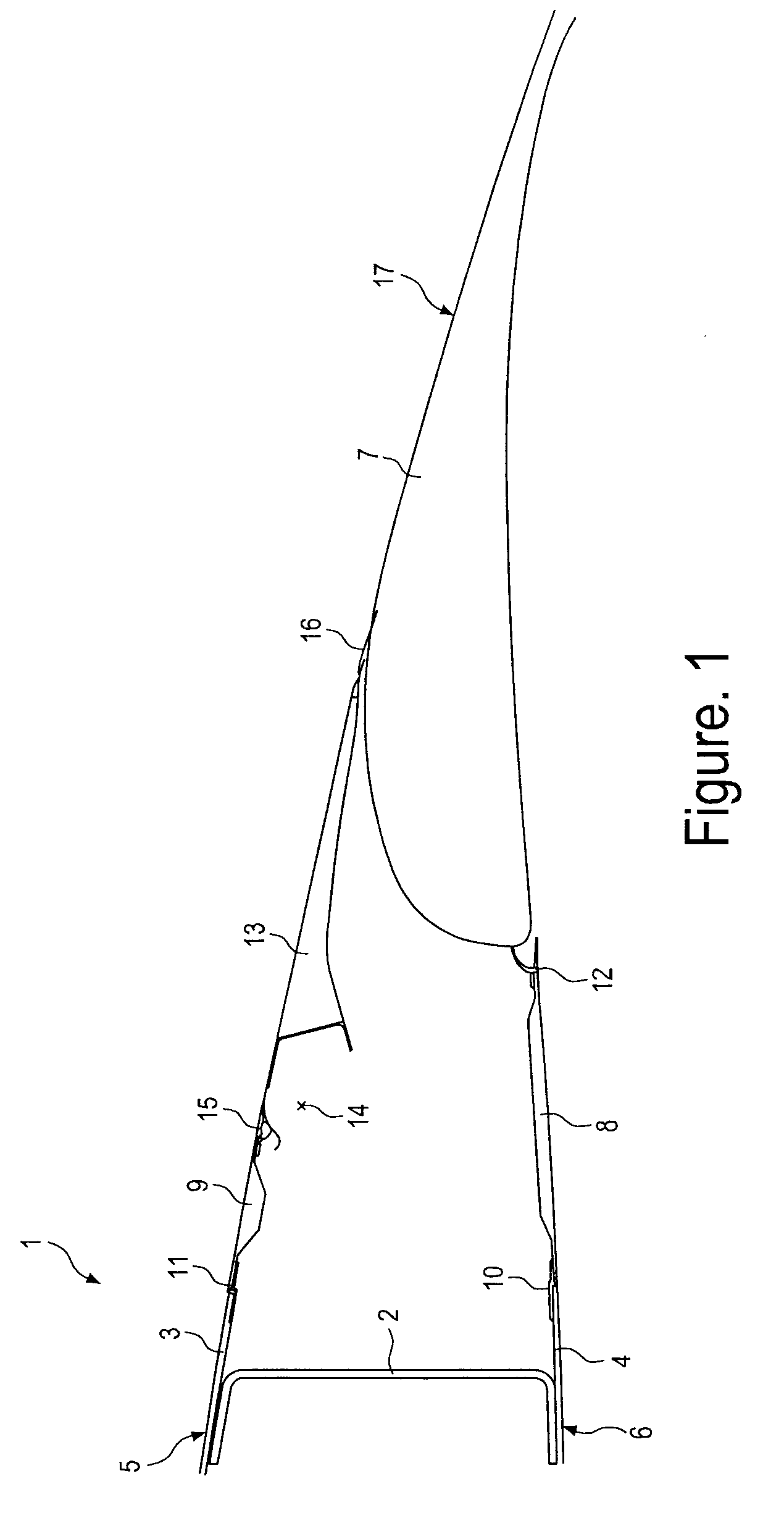
[0027]FIG. 1 shows a cross section through an aircraft wing trailing edge. The wing includes a fixed wing portion 1 comprising a rear spar 2, an upper wing cover 3 and a lower wing cover 4. Outer surfaces of the upper and lower wing covers 3, 4 form upper and lower aerodynamic surfaces 5, 6, respectively.

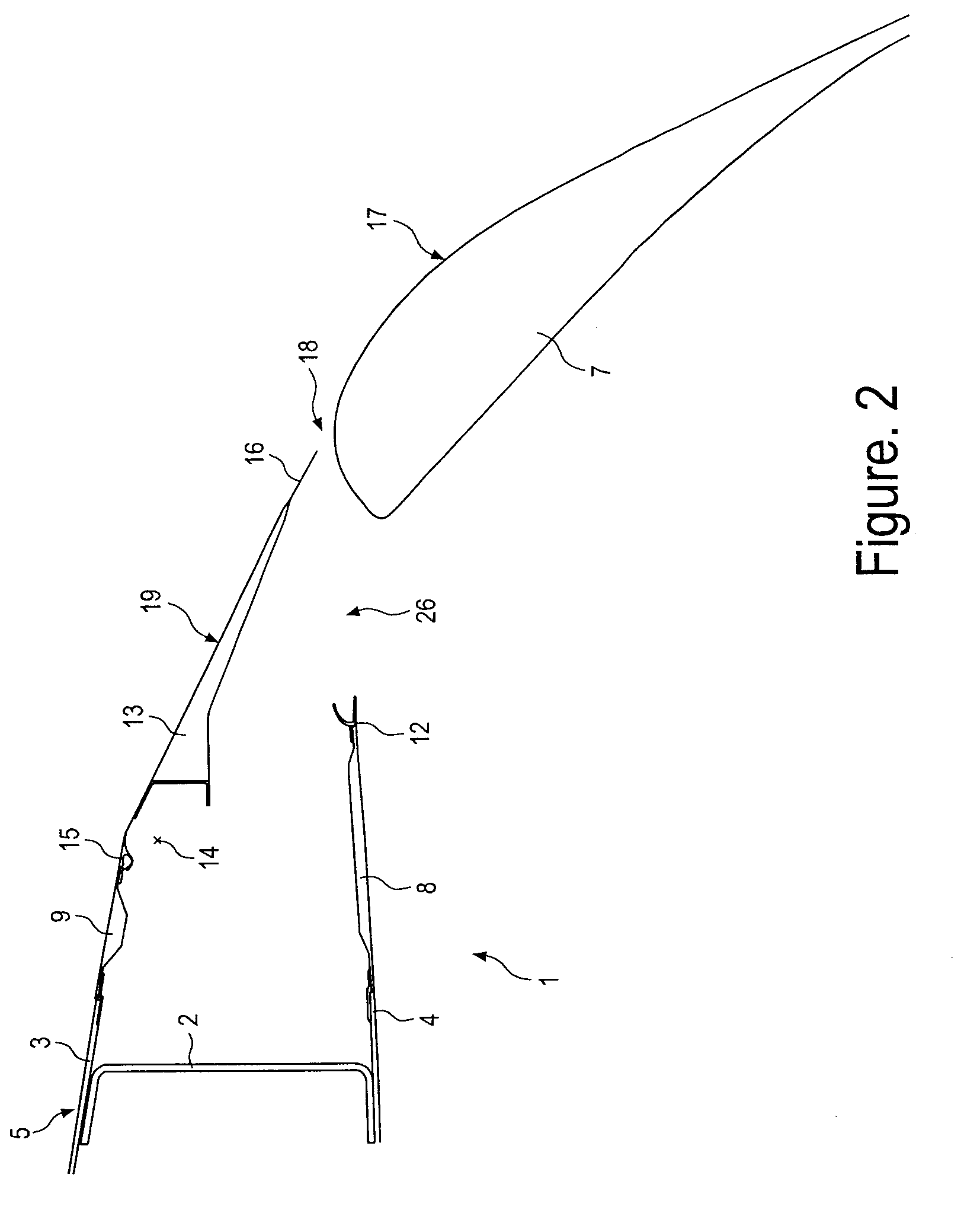
[0028]A trailing edge drop hinge flap 7 is mounted to the fixed wing portion 1 by a drop hinge mechanism (not shown). A lower trailing edge panel 8 and an upper trailing edge panel 9 form part of the overall wing profile and may be removed to access the drop hinge flap mechanism. The lower trailing edge panel 8 is connected to the lower wing cover 4 by a butt-strap 10, and the upper trailing edge panel 9 is connected to the upper wing cover 3 by a butt-strap 11. A seal member 12 seals between the lower trailing edge panel 8 and the flap 7 when the flap is in its retracted position as shown in FIG. 1.

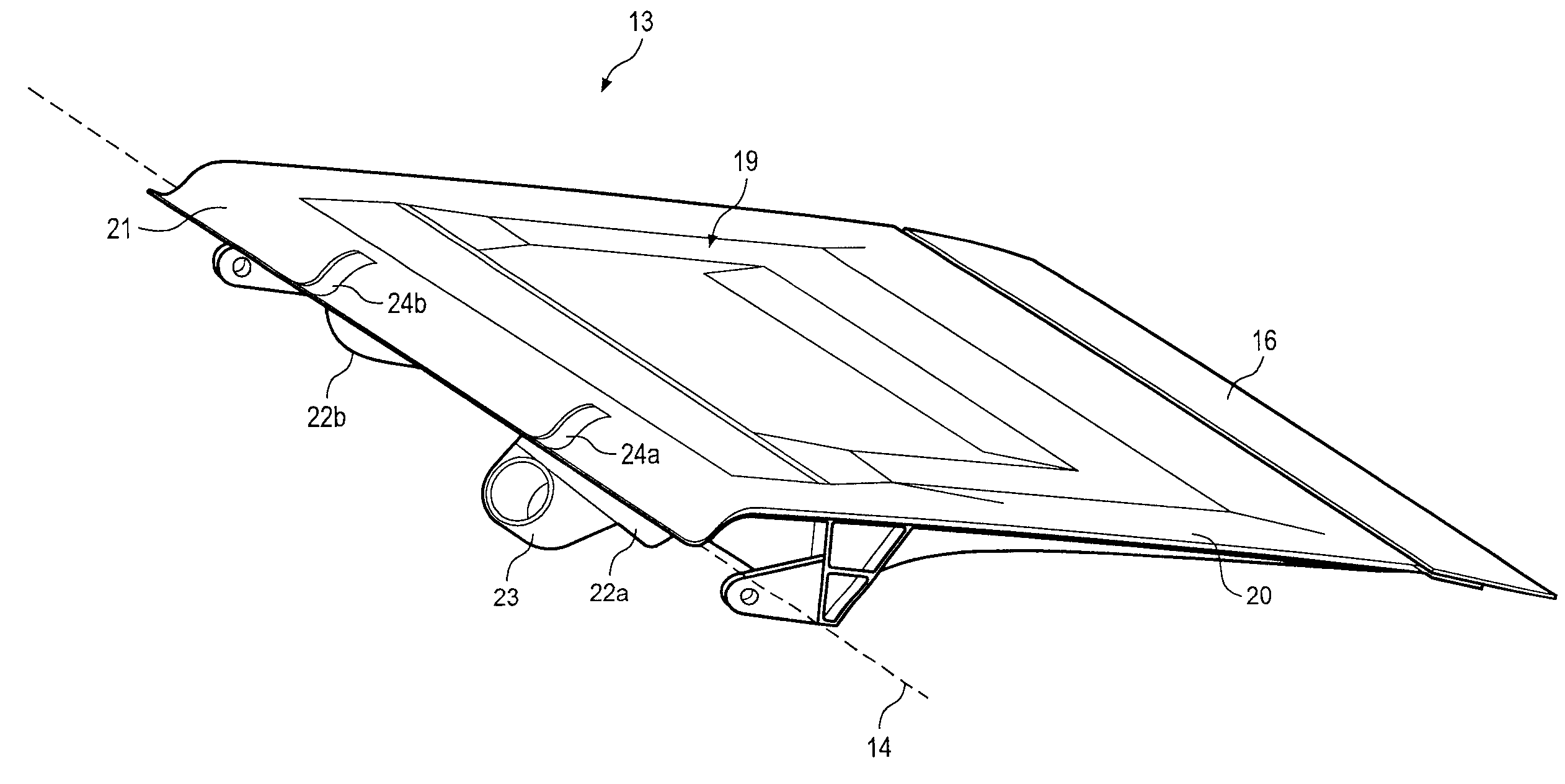
[0029]A drooping spoiler 13 is pivotally connected to the fixed wing portion 1 and i...


PUM


Abstract

A panel assembly for an aircraft including a panel having an upper aerodynamic surface and a leading edge, and a hinge fitting connected to an underside of the panel, defining a hinge line for the direction of rotation of the panel. The upper surface of the leading edge has an arcuate portion centered about the hinge line, and has an upturned portion forward of the arcuate portion. The panel assembly is pivotally connected to its hinge fitting to the trailing edge of the fixed wing portion and rotatable between a first position wherein the upper surfaces of the fixed wing portion and the panel are substantially flush, and a second position wherein the panel is rotated downwardly from the first position. A seal member attached to the trailing edge of the fixed wing portion, has a lower surface which seals against the upper surface of the panel during its movement.

Description

FIELD OF THE INVENTION[0001]The present invention relates to a panel assembly for an aircraft. In particular, though not exclusively, the invention relates to a flight control device assembly.BACKGROUND OF THE INVENTION[0002]Aircraft have flight control devices on the leading and / or trailing edges of their aerofoil sections, such as the wings, horizontal tailplane, and vertical tailplane. Common leading or trailing edge devices are slats, flaps, spoilers, ailerons, elevators, rudders and air brakes. These flight control devices typically operate to provide enhanced lift or drag during low speed flight, for example take-off / climb and landing / descent, or to provide pitch, roll and yaw control during any of the flight phases.[0003]When some of these flight control devices are deployed, a void is opened up in the upper and / or lower aerodynamic surfaces of the respective aerofoil section. It can be highly undesirable for an air path to be created between the lower and upper aerodynamic s...

Claims


Application Information

Patent Timeline
Patent Type & Authority Applications(United States)
IPC IPC(8): B64C3/50B64C3/00
CPCB64C7/00B64C9/16B64C9/02B64C9/14B64C9/18
Inventor MCALINDEN, JONWILDMAN, ERIC
Owner AIRBUS OPERATIONS LTD
Why Eureka
Try Eureka