Volume-based dispensing control method

a control method and volume technology, applied in the field of volume-based dispensing control methods, can solve the problems of reducing productivity, generating defective products, increasing manufacturing costs, etc., and achieve the effects of accurate control, rapid measurement, and enhanced efficiency of dispensing operations

Active Publication Date: 2010-12-30
PROTEC CO LTD
View PDF4 Cites 3 Cited by
  • Summary
  • Abstract
  • Description
  • Claims
  • Application Information

AI Technical Summary

Benefits of technology

[0010]The volume-based dispensing control method according to the present invention has an advantageous effect in that the quantity of the resin dispensed by a pump can be accurately controlled by accurately measuring the volume of the dispensed resin with an optical scanner.
[0011]Another advantageous effect of the present method resides in that the quantity of the dispensed resin can be rapidly measured, thereby enhancing the efficiency of a dispensing operation.

Problems solved by technology

If the dispensing quantity of resin is inaccurate, it may be a cause of generating defective products.
This results in reduced productivity and increased manufacturing cost.
This limits the accuracy of measurement made by the scale, which necessarily reduces the accuracy of controlling the dispensing quantity of resin.
This means that the dispensing quantity cannot be adjusted on a droplet-by-droplet basis according to the scale measurement method.
When using a screw-type pump, it is general that the quantity of the resin dispensed in proportion to the rotational angle of a screw cannot be accurately measured with a scale.
However, this poses a problem in that the total manufacturing cost of the dispenser becomes quite unreasonable.
In addition, use of the scale imposes a restriction on the weight measurement speed, consequently reducing the overall manufacturing speed.

Method used


Image

  • Volume-based dispensing control method
  • Volume-based dispensing control method
  • Volume-based dispensing control method

Examples


first embodiment

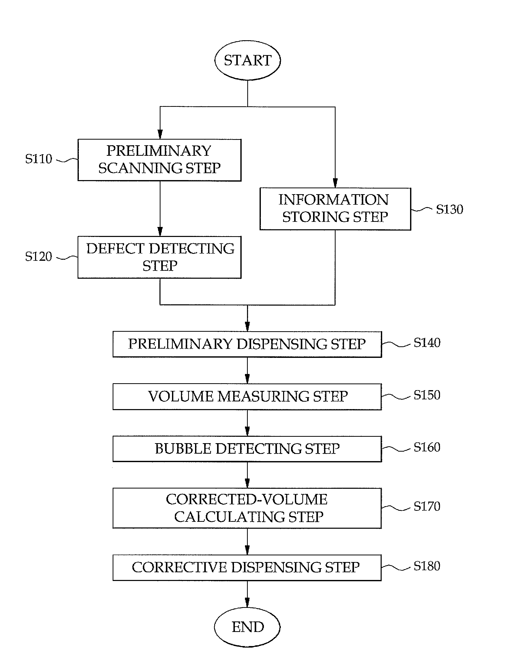
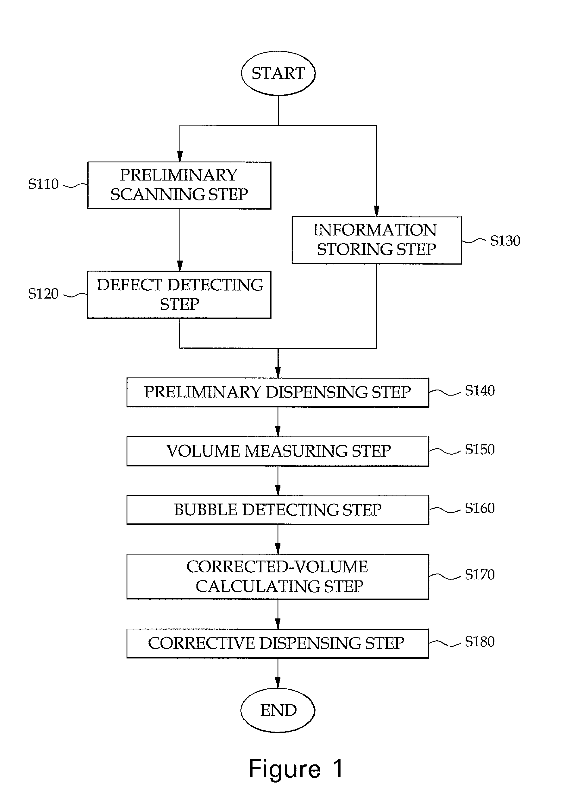
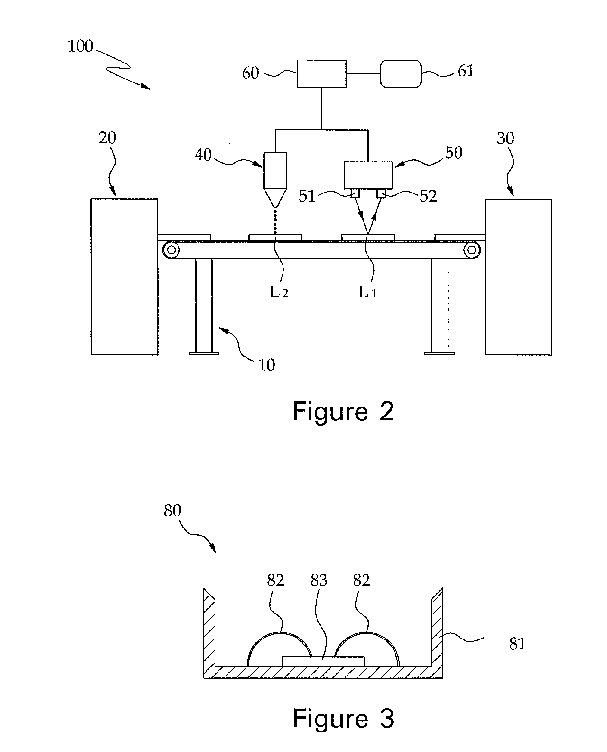
[0018]FIG. 1 is a flowchart illustrating a volume-based dispensing control method in accordance with the present invention, and FIG. 2 is a schematic diagram showing a dispenser by which to perform the volume-based dispensing control method illustrated in FIG. 1.

[0019]Referring first to FIG. 2, there is shown one example of a dispenser 100 by which to perform the volume-based dispensing control method of the present invention. The dispenser 100 includes a base 10, a loader 20, an unloader 30, a pump 40 and an optical scanner 50.

[0020]The loader 20 serves to feed substrates or lead frames L1 and L2 mounted with a plurality of workpieces 80 to the base 10. The following description will be directed to an instance where the lead frames L1 and L2 are fed by the loader 20. The loader 20 feeds the lead frames L1 and L2 in a state that the workpieces 80 are mounted to the lead frames L1 and L2. At the end of a dispensing operation, the lead frames L1 and L2 are transferred to and stored in...

second embodiment

[0037]Next, a volume-based dispensing control method in accordance with the present invention will be described with reference to FIG. 6.

[0038]In the volume-based dispensing control method of the second embodiment, the dispensing operation is performed by the dispenser 100 shown in FIG. 2. As distinguished from the method of the first embodiment in which the quantities of the silicon 84 to be dispensed vary with the LED elements 80, the method of the second embodiment is performed in case where the quantities of the silicon 84 to be dispensed are kept constant for all of the LED elements 80.

[0039]First, the total volume of the LED element 80 available prior to dispensing the silicon 84 is calculated by performing a preliminary scanning step S210 in which the three-dimensional shape of the LED element 80 is scanned in the state illustrated in FIG. 3.

[0040]Performed next is a preliminary dispensing step S220 in which the silicon 84 is dispensed on the LED element 80 in the quantity a ...


PUM

PropertyMeasurementUnit
volumeaaaaaaaaaa
optical scanneraaaaaaaaaa
volumesaaaaaaaaaa

Abstract

A volume-based dispensing control method is capable of enabling a pump to dispense a resin with greatly increased accuracy. The method includes: a preliminary dispensing step in which a resin is dispensed on one or more workpieces with a pump; a volume measuring step in which the workpieces passed through the preliminary dispensing step is scanned by an optical scanner to measure a dispensed resin volume; a corrected-volume calculating step in which a corrected volume of the resin to be additionally dispensed is calculated by using a difference between the dispensed resin volume measured in the volume measuring step and a predetermined dispensing volume; and a corrective dispensing step in which the resin is dispensed on the workpieces in light of the corrected volume calculated in the corrected-volume calculating step.

Description

FIELD OF THE INVENTION[0001]The present invention relates to a dispensing control method and, more particularly, to a volume-based dispensing control method capable of enabling a pump to dispense a resin with greatly increased accuracy.BACKGROUND OF THE INVENTION[0002]A dispenser for continuously dispensing a specified quantity of resin in the course of producing electronic parts is extensively used in a semiconductor manufacturing process. The resin used in the semiconductor manufacturing process serves to bond, cover and protect a semiconductor device. Examples of the dispensing step include an underfill step and an LED mold formation step, which steps are automatically performed by a resin-applying dispenser.[0003]In particular, the dispensing step is essential in an LED manufacturing process in order to dispense silicon containing a fluorescent material on a package provided with an LED chip to thereby adjust the color of light emitted from the LED chip and to structurally stabi...

Claims


Application Information

Patent Timeline
Patent Type & Authority Applications(United States)
IPC IPC(8): B29D11/00
CPCB29D11/00634B29D11/00807H01L2224/48091H01L2924/00014H01L21/56H01L23/28
Inventor YANG, KI MAN
Owner PROTEC CO LTD
Why Eureka
Try Eureka