LED illumination device

a technology of leds and illumination devices, which is applied in the direction of discharge tube main electrodes, semiconductor devices for light sources, lighting and heating apparatus, etc., can solve the problems of increased heat produced, lower heat resistance of leds, and a particular heat resistance, so as to reduce the number of leds and reduce the volume. , the effect of improving the heat dissipation

Inactive Publication Date: 2010-12-30
PYROSWIFT HOLDING CO LIMITED
View PDF2 Cites 4 Cited by
  • Summary
  • Abstract
  • Description
  • Claims
  • Application Information

AI Technical Summary

Benefits of technology

[0011]The present invention makes use of the protrusions formed on the vapor chamber and in a direct contact with the heat conducting pillars of the LEDs, such that the heat produced by the LED dies can be conducted to the vapor chamber and carried away through the vapor chamber quickly. In addition, th...

Problems solved by technology

However, it is inevitable to increase the heat produced when the intensity of illumination is improved.
In addition, the heat resistance of the LED, particularly for the high brightness LED, is lower than the heat resistance of a general incandescent light bulb.
A high-temperature heat source not only causes heat to be accumulated around the LED and lowers the light emitting ...

Method used


Image

  • LED illumination device
  • LED illumination device
  • LED illumination device

Examples


Embodiment Construction

[0016]The technical characteristics, features and advantages of the present invention will become apparent in the following detailed description of the preferred embodiments with reference to the accompanying drawings. The drawings are provided for reference and illustration only, but not intended for limiting the present invention.

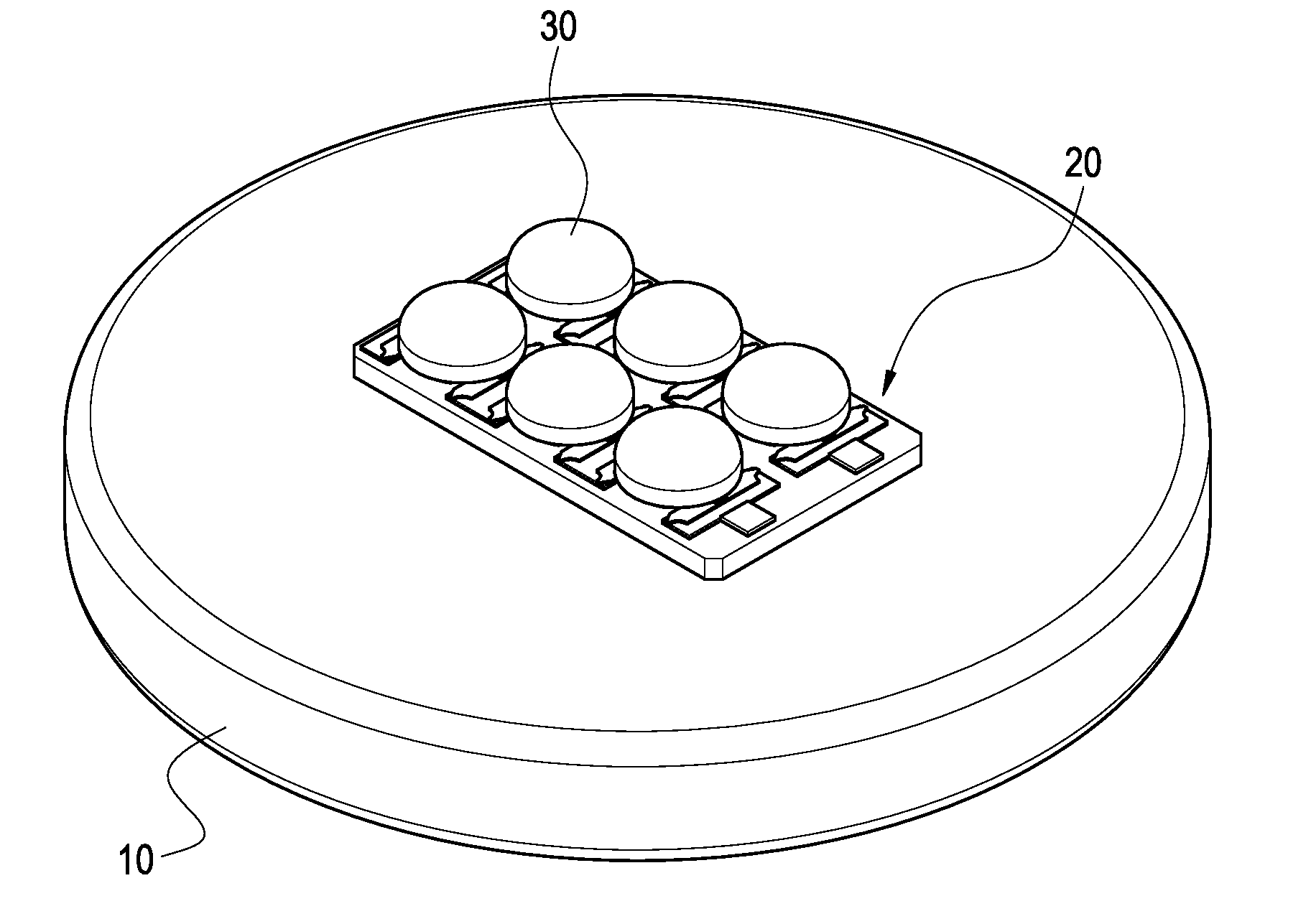
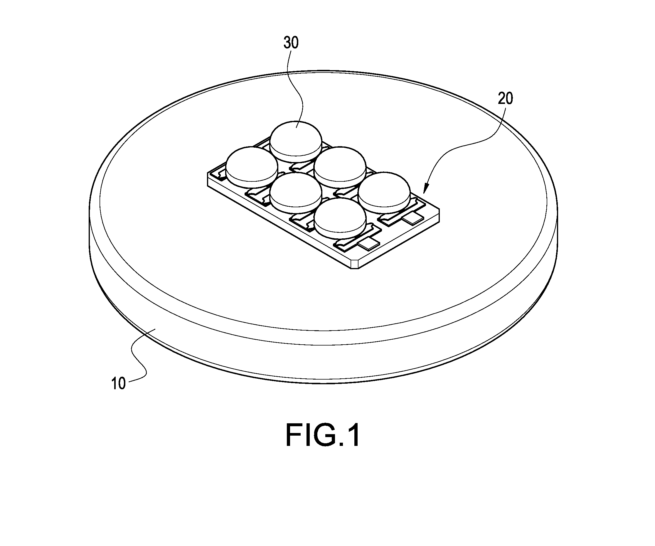
[0017]With reference to FIG. 1 for a perspective view of an LED illumination device of the present invention, the LED illumination device comprises a vapor chamber 10, a circuit board 20, and at least one LED 30.

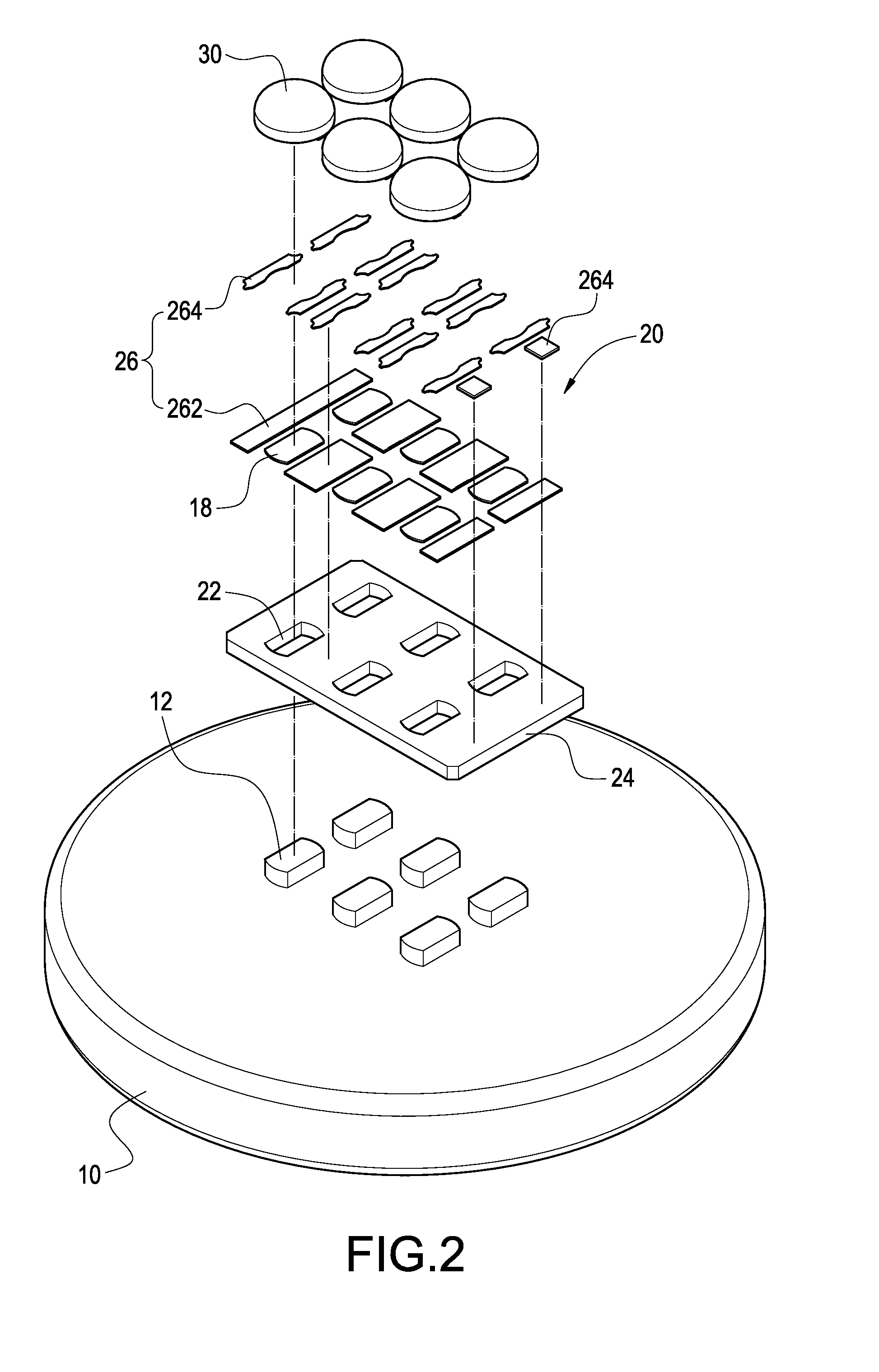
[0018]With reference to FIGS. 2 and 3 for an exploded view and a cross-sectional view of an LED illumination device of the present invention respectively, the vapor chamber 10 includes a hollow metal casing, a capillary tissue 14 attached onto an internal wall of the casing, and a working liquid 16 filled into the casing. In addition, at least one protrusion 12 is formed on a surface of the vapor chamber 10. In this preferred embodiment, the vapor...


PUM


Abstract

A light emitting diode (LED) illumination device includes a vapor chamber, a circuit board and at least one LED. At least one protrusion is formed on a surface of the vapor chamber, and a heat conducting tin layer is formed on the protrusion. The circuit board includes at least one through hole for passing the protrusion. The circuit board is formed by sequentially stacking an insulating layer and a heat conducting layer. The LEDs are installed on and contacted with the protrusions respectively, and each LED has two pins electrically connected to the circuit board. The LED device of the present invention is in a direct contact with the protrusion of the LED, such that the heat dissipated from the LED can be conducted to the vapor chamber, and then the vapor chamber carries away the heat quickly.

Description

BACKGROUND OF THE INVENTION[0001]1. Field of the Invention[0002]The present invention relates to an illumination device, and more particular to a light emitting diode (LED) illumination device.[0003]2. Description of Prior Art[0004]Light emitting diode (LED) has the power-saving and long-life features, and its brightness is improved continuously, and thus LED is applied to electronic devices and indoor or outdoor illumination lamps extensively.[0005]Most indoor or outdoor illumination lamps combine a plurality of high brightness LEDs to form an LED lamp module to enhance the range and intensity of the illumination lamps. However, it is inevitable to increase the heat produced when the intensity of illumination is improved. In addition, the heat resistance of the LED, particularly for the high brightness LED, is lower than the heat resistance of a general incandescent light bulb. A high-temperature heat source not only causes heat to be accumulated around the LED and lowers the light...

Claims


Application Information

Patent Timeline
IPC IPC(8): H01J1/02
CPCF21K9/00F21V29/004F21Y2101/02F21Y2105/001H05K1/021F21V29/20H05K2201/064H05K2201/09054H05K2201/10106H05K2201/10477F21V29/006H05K1/0272F21V29/51F21Y2105/10F21Y2115/10
Inventor WANG, PEI-CHOA
Owner PYROSWIFT HOLDING CO LIMITED
Why Eureka
Try Eureka