Reactive power compensation circuit

a compensation circuit and reactive power technology, applied in the field of reactive power, can solve the problems of providing reactive power, affecting the operation of the circuit, etc., and achieve the effect of reducing the voltage to a level significantly lower, reducing the disadvantage, and reducing the disadvantag

Inactive Publication Date: 2010-12-30
NISENBLAT POL
View PDF7 Cites 17 Cited by
  • Summary
  • Abstract
  • Description
  • Claims
  • Application Information

AI Technical Summary

Problems solved by technology

Reactive power flows can give rise to substantial voltage changes across the system, meaning that it is necessary to maintain reactive power balances.
A main disadvantage of SVC is that it provides reactive power proportional to the second power of the voltage (V2).
At normal network operation conditions when network voltage varies within a range of ±10% that disadvantage is insignificant.
However, in some applications, such as large load variations such as an AC motor start-up or grid fault conditions, voltage may drop to levels significantly lower than defined as

Method used


Image

  • Reactive power compensation circuit
  • Reactive power compensation circuit
  • Reactive power compensation circuit

Examples


Embodiment Construction

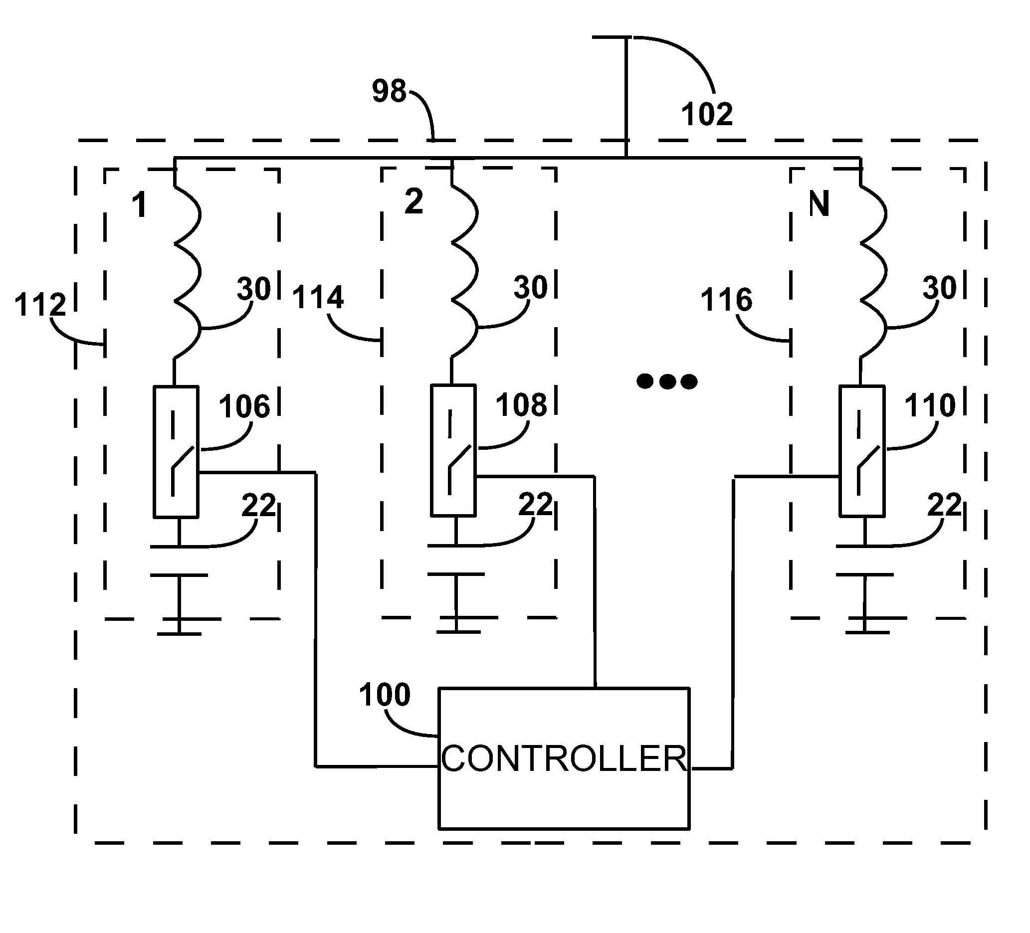
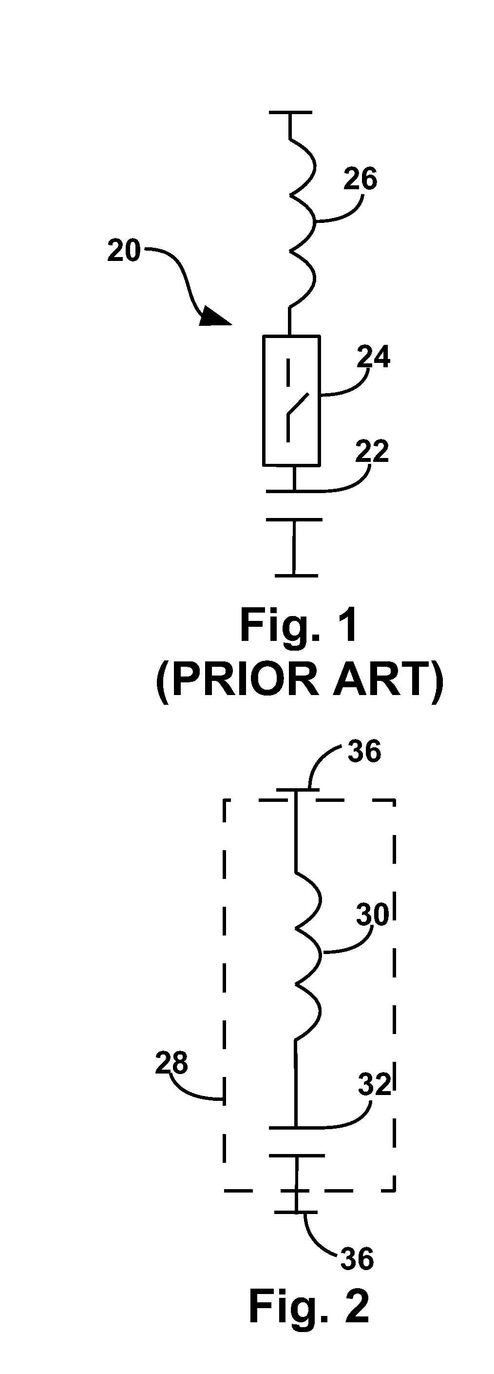
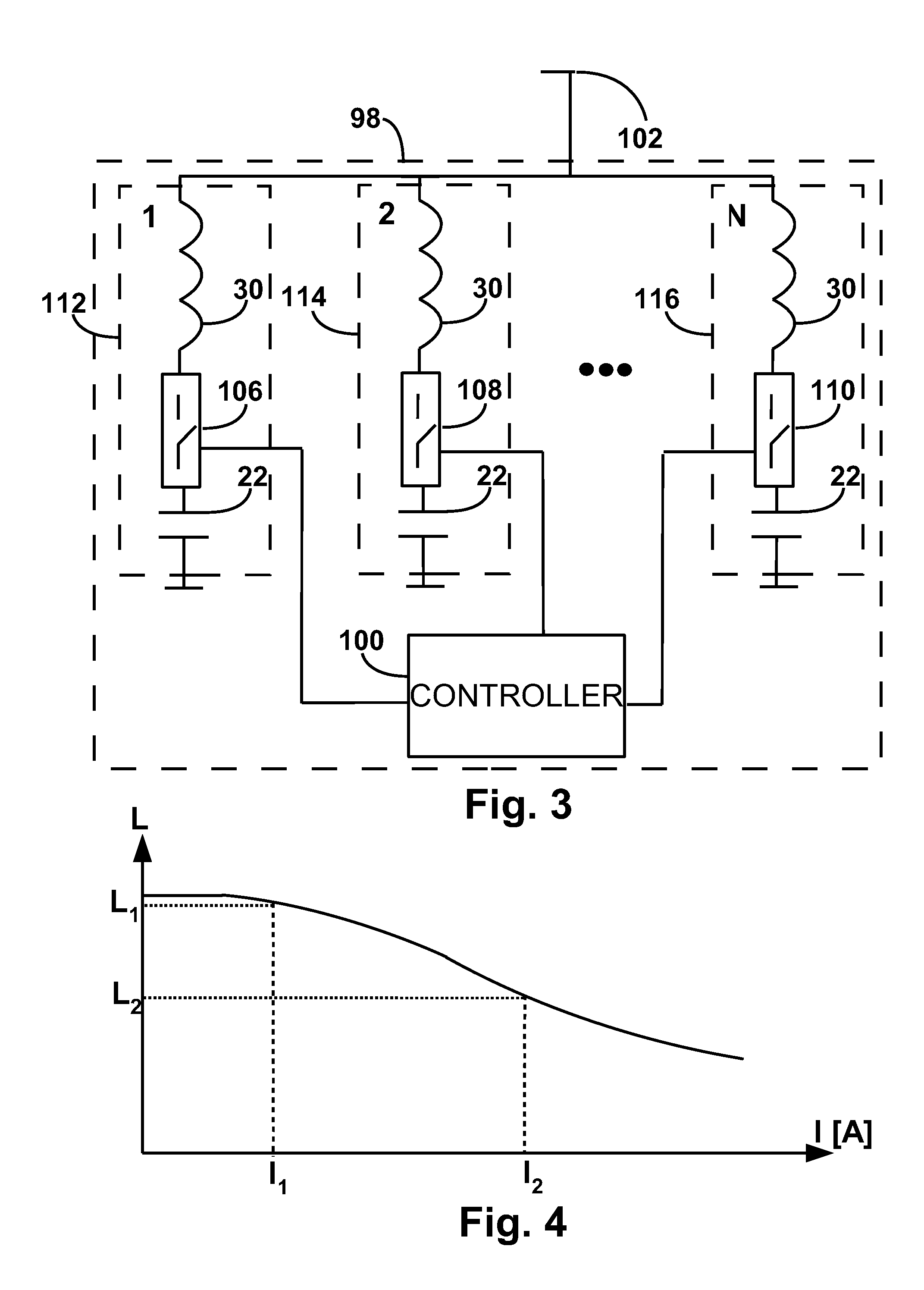
[0012]In accordance with the present invention appliances for absorbing reactive power such as inductors and appliances for generating reactive power such as capacitors are associated with switching appliances and with a controlling mechanism for delivering reactive power compensation to electrical networks of either low or high voltage. A schematic description of a power compensation branch circuitry employed in accordance with the present invention is described in FIG. 2 to which reference is now made. Power compensation branch 28 includes inductor 30 and capacitor 32. A relationship between I, V and X in the branch is given by equation 1 as follows:

I=VXC-XL(1)

Where V is the voltage across branch 28, XL is the inductor reactance in the fundamental frequency and XC is the capacitor reactance in the fundamental frequency. In accordance with one embodiment of the present invention the resulting impedance of the branch in the overall is a capacitive one.

[0013]In order to better explai...


PUM


Abstract

A compensation circuitry for providing reactive power to a network includes an inductance means and a capacitor means associated with switching appliances and with a controlling mechanism. The compensation circuitry is used for delivering reactive power compensation to electrical networks of either low or high voltage. The inductance means and the capacitor means are connected serially, thereby bringing the circuitry to a virtual gain selected from a group consisting of virtual inductance gain (VIG) or virtual capacitance gain (VCG), and wherein the virtual gain selected from the group is above the absolute value of 1.5.

Description

FIELD OF THE INVENTION[0001]The present invention is in the field of reactive power. More specifically, the present invention relates to reactive power compensation.BACKGROUND OF THE INVENTION[0002]Reactive power is the power used by some devices to create an electromagnetic field. This power is expressed in kvar. The consumption of reactive power is a characteristic of electric devices which use the inductive properties of an alternating electromagnetic field, i.e. mostly motors and transformers. Reactive power is different from active power, expressed in kW, which is converted into work and heat. The total electrical power of a device is the vector difference of both power components (reactive and active) and is called apparent power. This phenomenon of reactive power may have consequences for electrical networks of both low and high voltage. Devices which store energy by virtue of a magnetic field produced by a flow of current are said to absorb reactive power; those which store ...

Claims


Application Information

Patent Timeline
IPC IPC(8): G05F1/70
CPCY02E40/30H02J3/1828H02J3/1864
Inventor NISENBLAT, POL
Owner NISENBLAT POL
Why Eureka
Try Eureka