
Frequency synthesizer and polar transmitter having the same

Inactive Publication Date: 2010-12-30
SAMSUNG ELECTRONICS CO LTD
View PDF6 Cites 20 Cited by
  • Summary
  • Abstract
  • Description
  • Claims
  • Application Information

AI Technical Summary

Benefits of technology

[0021]According to an exemplary embodiment of the inventive concept, a polar transmitter includes a data processing unit, a frequency synthesizer and a power amplifier. The data processing unit processes baseband data and converts the processed baseband data to an amplitude signal and a phase signal. The frequency synthesizer generates an oscillation frequency signal based on a reference frequency signal and the phase signal. The power amplifier synthesizes the oscillation frequency signal and the amplitude signal to output a transmission signal. The frequency synthesize

Problems solved by technology

However, it may be difficult to meet certain specifications when employing the integer-N technique due to a trade-off between loop bandwidth and channel spacing.
However, the fractional-N technique results in the generation of fractional spurious signals (i.e., spurs).
However, frequency synthesizers incorporating sigma / delta modulators suffer from sigma / delta noise (e.g., a quantization noise).

Method used


Image

  • Frequency synthesizer and polar transmitter having the same
  • Frequency synthesizer and polar transmitter having the same
  • Frequency synthesizer and polar transmitter having the same

Examples


Embodiment Construction

[0037]Exemplary embodiments of the inventive concept will be described more fully hereinafter with reference to the accompanying drawings. The present inventive concept may, however, be embodied in many different forms and should not be construed as limited to the exemplary embodiments set forth herein. In the drawings, like numerals refer to like elements throughout.

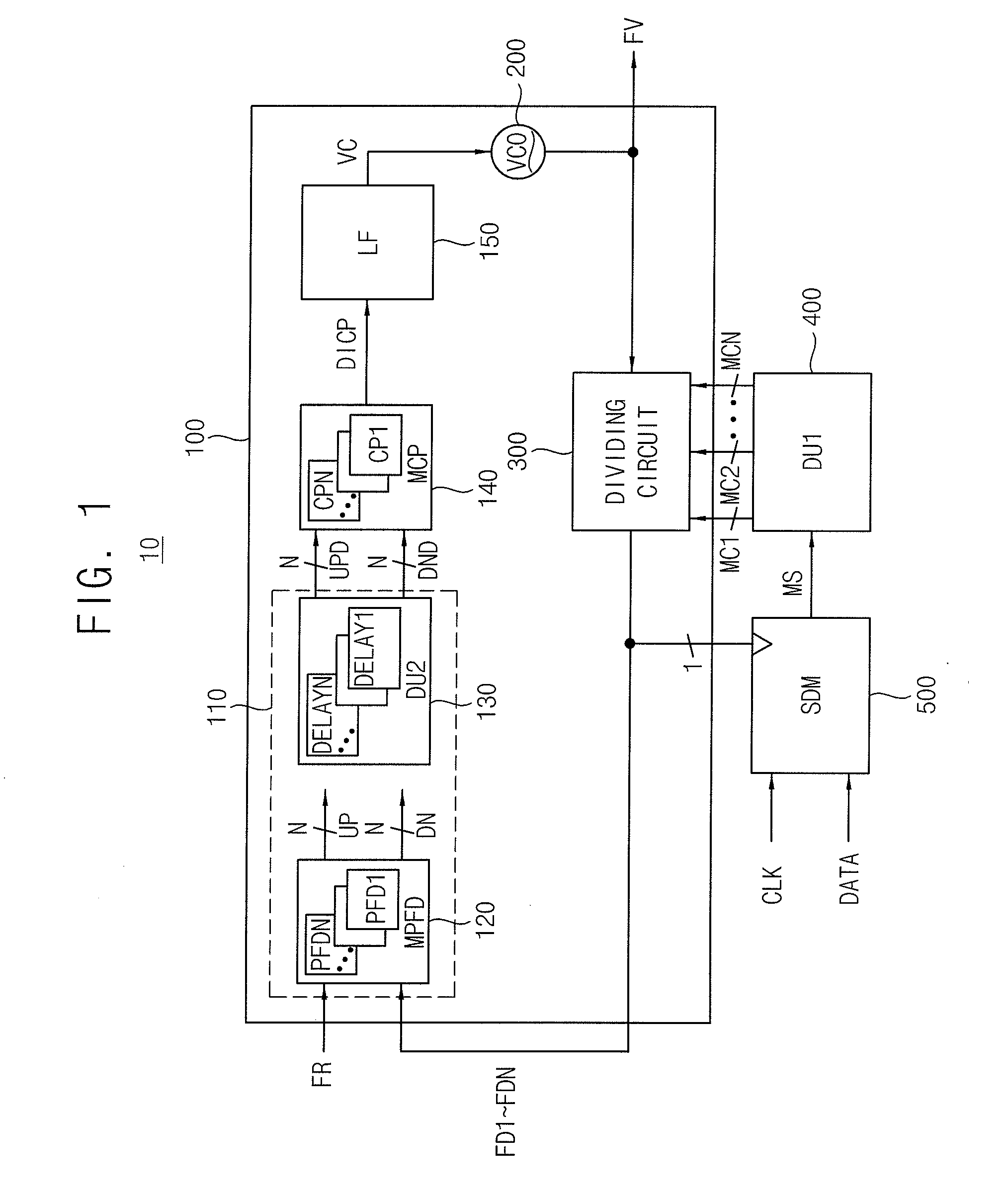
[0038]FIG. 1 is a block diagram illustrating a frequency synthesizer according to an exemplary embodiment of the inventive concept. Referring to FIG. 1, a frequency synthesizer 10 includes a phase-locked loop (PLL) 100, a first delay unit 400, and a sigma-delta modulator (SDM) 500.

[0039]The PLL 100 includes distributed phase detector circuit 110, a multiple charge pump 140, a loop filter 150, a voltage-controlled oscillator (VCO) 200 and a dividing circuit 300. The distributed phase detector circuit 110 includes a multiple phase detector 120 and a second delay unit 130.

[0040]The multiple phase detector 120 includes a pl...


PUM


Abstract

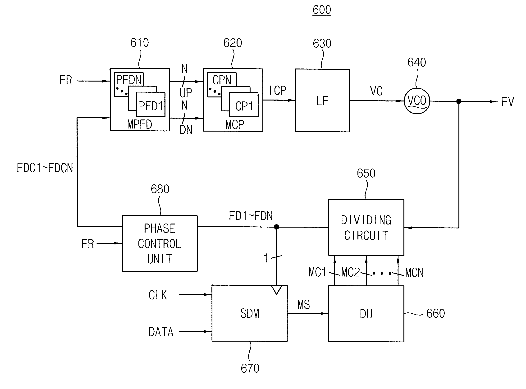
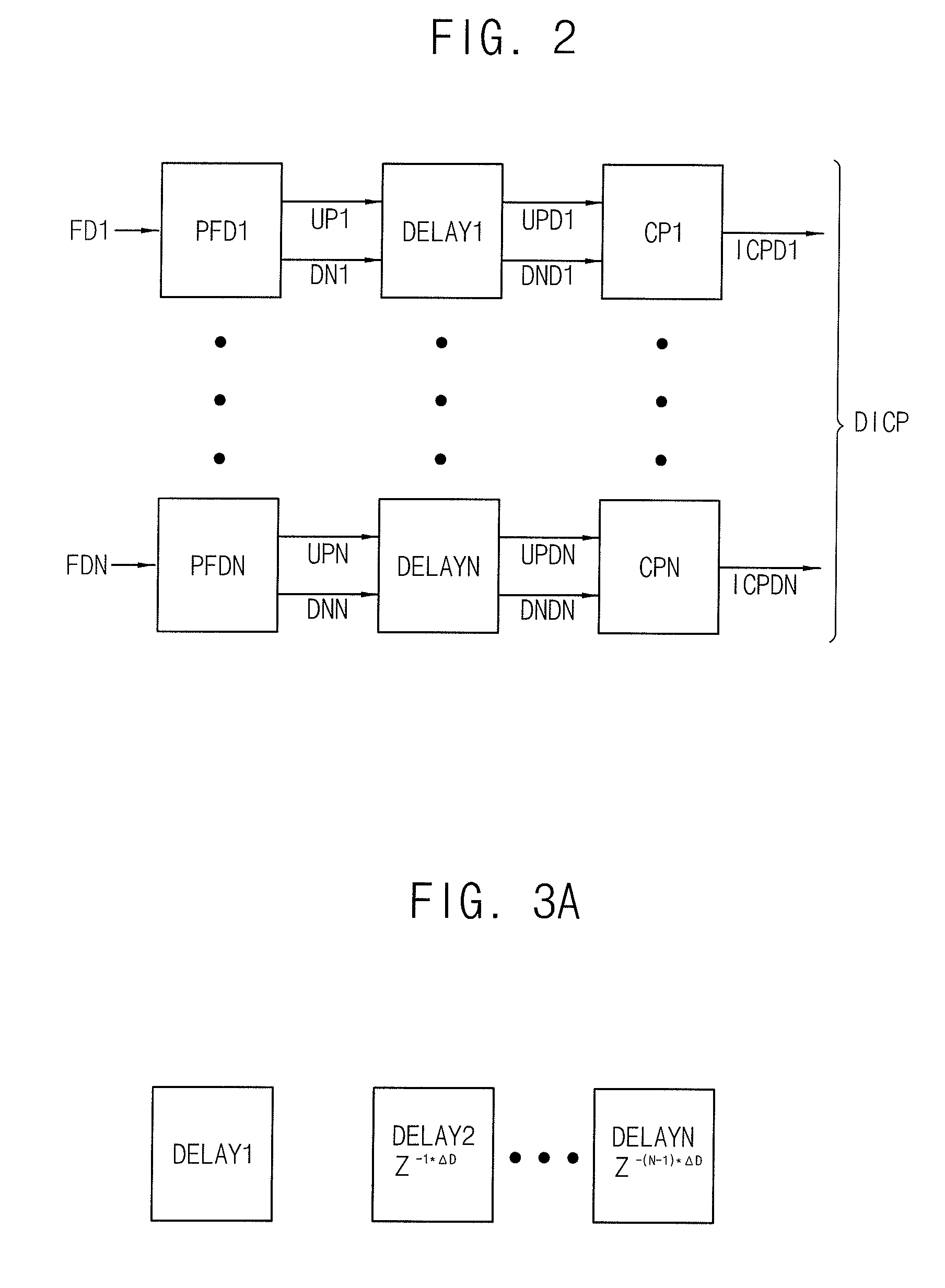
A frequency synthesizer includes a distributed phase detector circuit, a multiple charge pump, a loop filter, a voltage-controlled oscillator and a dividing circuit. The distributed phase detector circuit delays an up signal and a down signal to generate a delayed up signal and a delayed down signal. The multiple charge pump generates a distributed current signal including a plurality of current pulse signals. Each of the current pulse signal is based on each bit of the delayed up signal and the delayed down signal. The loop filter filters the distributed current signal to generate a control voltage. The voltage-controlled oscillator generates an oscillation frequency signal based on the control voltage. The dividing circuit divides the oscillation frequency signal to generate a plurality of division frequency signals in response to a plurality of control signals, where the frequency signals are fedback to the distributed phase detector circuit.

Description

CROSS-REFERENCE TO RELATED APPLICATIONS[0001]This application claims priority under 35 USC §119 to Korean Patent Application No. 2009-0058018, filed on Jun. 29, 2009 in the Korean Intellectual Property Office (KIPO), the disclosure of which is incorporated by reference in its entirety herein.BACKGROUND[0002]1. Technical Field[0003]Exemplary embodiments of the inventive concept relate to frequency synthesizing, and more particularly to a frequency synthezier and a polar transmitter having the same.[0004]2. Discussion of Related Art[0005]A phase-locked loop (PLL) is a closed-loop frequency-control system based on the phase difference between an input signal and a feedback signal of a controlled oscillator. PLL circuits may be used to synthesize a desired signal frequency. A frequency synthesizer of a PLL may employ an integer-N technique and a fractional-N technique. The integer-N technique uses a fixed integer N to divide an output frequency. The fractional-N technique uses a number ...

Claims


Application Information

Patent Timeline
IPC IPC(8): H04L27/36H03L7/087
CPCH03L7/081H03L7/1976H03L7/193H03L7/087H03D7/00H04B1/04
Inventor KO, SANG-SOO
Owner SAMSUNG ELECTRONICS CO LTD
Learn More