Magnetic confinement device

Inactive Publication Date: 2010-12-30
KOTSCHENREUTHER MICHAEL T +2
View PDF14 Cites 10 Cited by
  • Summary
  • Abstract
  • Description
  • Claims
  • Application Information

AI Technical Summary

Benefits of technology

[0015]Additional advantages will be set forth in part in the description which follows, and in part will be obvious from the description, or may be learned by practice. Other advantages will be realized and attained by means of the elements and combinations particularly pointed out in the appended claims. It is to be understood that both the foregoing general description and the following detailed description are exemplary and explanatory only and are not restrictive of the invention, as claimed.

Problems solved by technology

While fusion is a spectacularly successful energy source for the sun and the stars, the practicalities of harnessing fusion on Earth are technically challenging, given that to sustain fusion, a plasma (a gas consisting of charged ions and electrons), or an ionized gas, has to be confined and heated to millions of degrees Celsius in a fusion reactor for a sufficient period of time to enable the fusion reaction to occur.
The science behind fusion is well advanced, rooted in more than 100 years of nuclear physics and electromagnetic and kinetic theory, yet current engineering constraints make the practical use of nuclear fusion very challenging.
However, in reality, particles and energy very slowly escape magnetic confinement in a direction perpendicular to the magnetic surfaces as a result of particle collisions with one another or turbulence in the plasma.
High “scrape off flux” creates a multitude of challenges.
These neutrons cause a degradation of many important material properties, making it extremely difficult for a divertor plate to handle both the high heat fluxes and neutron fluxes without having to be replaced frequently.
Periodically replacing the damaged components is very time consuming and requires the fusion reaction to be shut off.
Further, trying to reduce the “scrape off flux” by injecting impurities to radiate energy before it reaches divertor plates is not workable because the density of power coming out of the plasma becomes so high that it seriously degrades the plasma confinement, which results in a serious reduction of the fusion reaction rate in the core plasma.
However, this approach significantly increases the reactor cost, and hence the cost of any energy produced with it, to levels that are economically non-competitive with other methods for the generation of power or neutrons.
However, high “scrape off flux” is a critical roadblock for these fusion applications.

Method used


Image

  • Magnetic confinement device
  • Magnetic confinement device
  • Magnetic confinement device

Examples


examples

[0109]The following examples are put forth so as to provide those of ordinary skill in the art with a complete disclosure and description of how the compounds, compositions, articles, devices and / or methods claimed herein are made and evaluated, and are intended to be purely exemplary and are not intended to limit the disclosure. Efforts have been made to ensure accuracy with respect to numbers (e.g., amounts, temperature, etc.), but some errors and deviations should be accounted for. Unless indicated otherwise, parts are parts by weight, temperature is in ° C. or is at ambient temperature, and pressure is at or near atmospheric.

[0110]1. Modified Design of Steady State Superconducting Tokamak

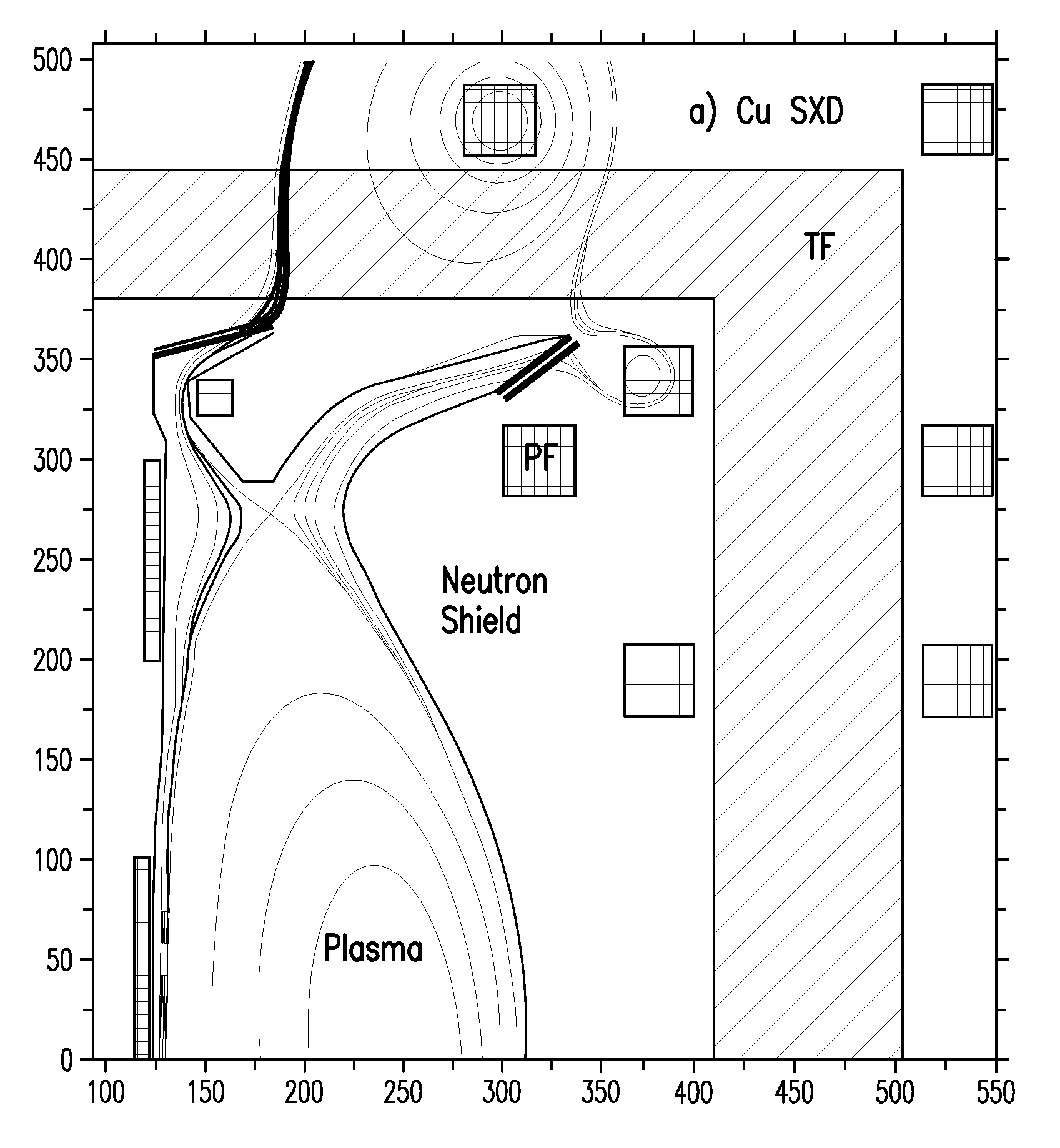
[0111]FIG. 6, modified from FIG. 1 in Bora et al., Brazilian Journal of Physics Vol. 32, no. 1, pg. 193-216, March 2002, the contents of which are incorporated herein by reference, displays an exemplary modified design of a Steady State Superconduction Tokamak (SST). Various parameters for the S...


PUM


Abstract

Disclosed is a device comprising a chamber enclosed by walls about a central axis. The chamber has an inner radius and an outer radius relative to the central axis and is configured to magnetically contain a core plasma. The device is further comprised of a divertor plate configured for receiving exhaust heat. The divertor plate has a divertor radius relative to the central axis. The divertor radius is greater than or equal to the sum of a plasma minor radius and a major radius of the peak point closest to the corresponding divertor plate. The device can be used for containing a fusion plasma, as a compact fusion neutron source, or as a compact fusion energy source. Methods of exhausting heat from such a device when plasma is present therein are also described. This abstract is intended for use as a scanning tool only and is not intended to be limiting.

Description

CROSS REFERENCE TO RELATED APPLICATION[0001]This application is a continuation application of co-pending U.S. patent application Ser. No. 12 / 197,736 filed on Aug. 25, 2008, which is fully incorporated herein by reference and made a part hereof.ACKNOWLEDGEMENT[0002]This invention was made with U.S. government support under Grant Nos. DE-FG02-04ER54742 and DE-FG02-04ER54754 awarded by the United States Department of Energy. The government has certain rights in the invention.BACKGROUND[0003]Nuclear fusion is an energy source derived from nuclear combinations of light elements into heavier elements resulting in a release of energy. In fusion, two light nuclei (such as deuterium and tritium) combine into one new nucleus (such as helium) and release enormous energy and another particle (such as a neutron in the case of the fusion of deuterium and tritium) in the process. While fusion is a spectacularly successful energy source for the sun and the stars, the practicalities of harnessing fu...

Claims


Application Information

Patent Timeline
IPC IPC(8): G21B1/05H05H1/12G21B1/11
CPCG21B1/05G21B1/057G21B1/13Y02E30/128H05H3/06Y02E30/126H05H1/12Y02E30/10
Inventor KOTSCHENREUTHER, MICHAEL T.VALANJU, PRASHANT M.MAHAJAN, SWADESH M.
Owner KOTSCHENREUTHER MICHAEL T
Why Eureka
Try Eureka