
Crosstalk Estimation and Power Setting Based on Interpolation in a Multi-Channel Communication System

a multi-channel communication system and crosstalk estimation technology, applied in the field of communication systems, can solve the problems of affecting the performance of the system, and affecting the operation speed of the system, so as to achieve the effect of reducing the impact of active lines, enhancing the speed of operation within the system, and less tim

Active Publication Date: 2010-12-30
RPX CORP
View PDF4 Cites 52 Cited by
  • Summary
  • Abstract
  • Description
  • Claims
  • Application Information

AI Technical Summary

Benefits of technology

The present invention provides techniques for estimating crosstalk coefficients and utilizing them in power control and preceding applications. By obtaining estimated crosstalk coefficients and setting power levels based on them, interference between lines can be minimized, while maintaining desired performance characteristics in the active lines. This results in faster operation within the system and minimal impact on active lines. The technique uses linear-model interpolation to obtain the estimated crosstalk coefficients, which can be quickly obtained compared to other methods.

Problems solved by technology

A problem that can arise in multiple channel communication systems relates to crosstalk between the various channels, also referred to as inter-channel crosstalk.
One of the major impairments in such systems is crosstalk between multiple subscriber lines within the same binder or across binders.
Thus, a transmission on one subscriber line may be detected on other subscriber lines, leading to interference that can degrade the throughput performance of the system.
More generally, a given “victim” channel may experience crosstalk from multiple “disturber” channels, again leading to undesirable interference.

Method used


Image

  • Crosstalk Estimation and Power Setting Based on Interpolation in a Multi-Channel Communication System
  • Crosstalk Estimation and Power Setting Based on Interpolation in a Multi-Channel Communication System
  • Crosstalk Estimation and Power Setting Based on Interpolation in a Multi-Channel Communication System

Examples


Embodiment Construction

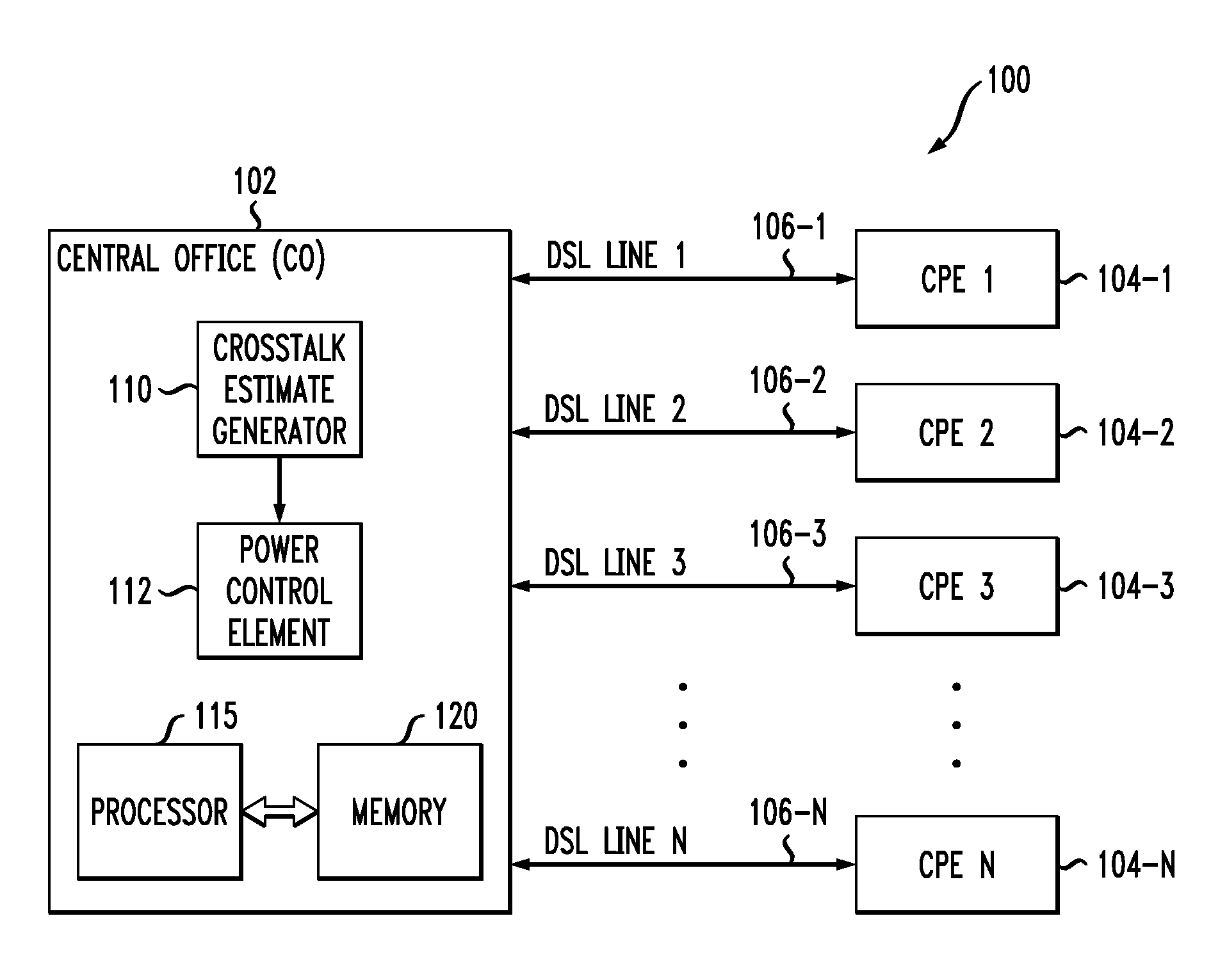
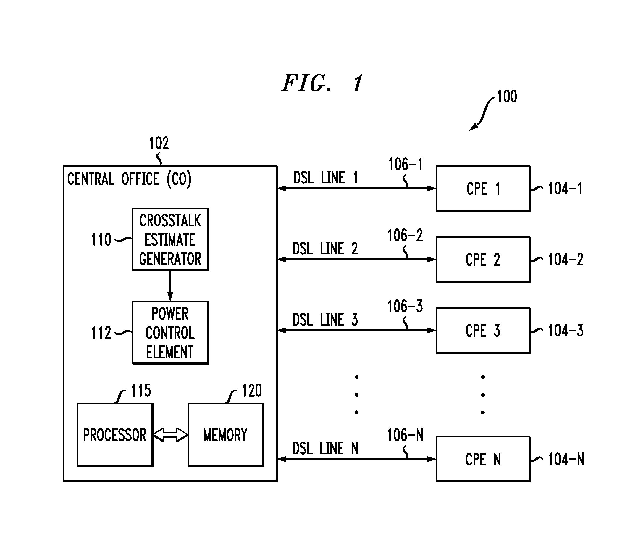
[0022]The present invention will be illustrated herein in conjunction with exemplary communication systems and associated techniques for obtaining crosstalk estimates in such systems. The crosstalk estimates may be used in conjunction with joining subscriber lines or other communication channels to a group of active channels in such systems, or for other line management functions. It should be understood, however, that the invention is not limited to use with the particular types of communication systems and channel estimation applications disclosed. The invention can be implemented in a wide variety of other communication systems, using alternative techniques for obtaining channel coefficient estimates, and in numerous alternative applications involving the use of such estimates. For example, although illustrated in the context of DSL systems based on DMT modulation, the disclosed techniques can be adapted in a straightforward manner to a variety of other types of wired or wireless...


PUM


Abstract

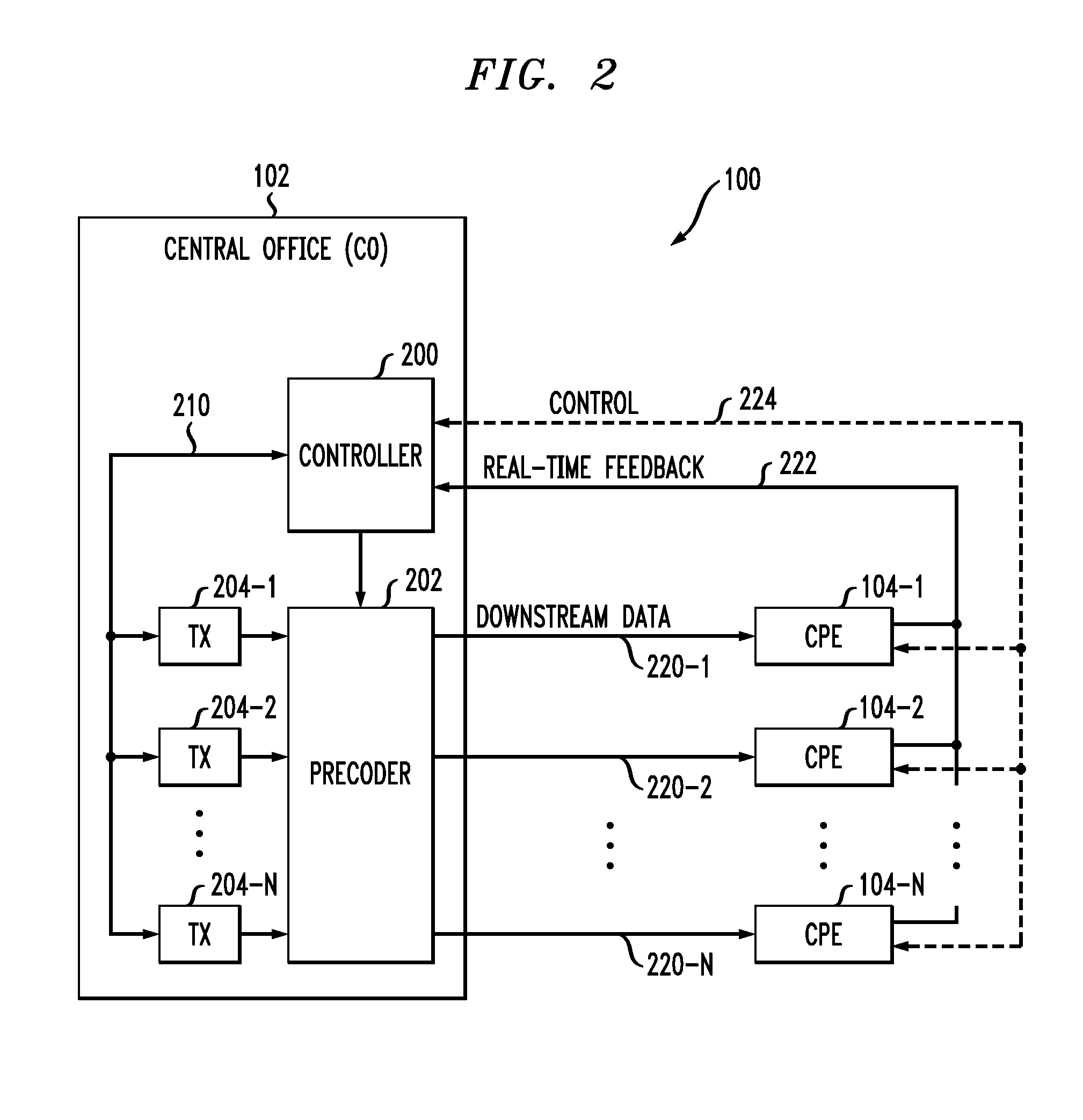
An access node of a communication system comprises a plurality of transmitters adapted for communication with at least one receiver over a plurality of channels. The access node is operative to obtain estimated crosstalk coefficients between a joining channel and an active channel, and to set a power level of at least one signal transmitted over the joining channel based on the estimated crosstalk coefficients. The access node obtains the estimated crosstalk coefficients by first obtaining a subset of the estimated crosstalk coefficients and subsequently determining additional ones of the estimated crosstalk coefficients by applying an interpolation process to the estimated crosstalk coefficients in the subset. The access node sets the power level of the signal transmitted over the joining channel in a manner that ensures maintenance of a desired performance characteristic for the active channel.

Description

FIELD OF THE INVENTION[0001]The present invention relates generally to communication systems, and more particularly to techniques for controlling crosstalk between communication channels in such systems.BACKGROUND OF THE INVENTION[0002]As is well known, a communication system may utilize multiple communication channels to communicate signals between transmitters and receivers of the system. For example, multiple channels may be used to separate different transmitted data signals from one another, or to provide an increased data rate.[0003]A problem that can arise in multiple channel communication systems relates to crosstalk between the various channels, also referred to as inter-channel crosstalk. For example, digital subscriber line (DSL) broadband access systems typically employ discrete multi-tone (DMT) modulation over twisted-pair copper wires. One of the major impairments in such systems is crosstalk between multiple subscriber lines within the same binder or across binders. T...

Claims


Application Information

Patent Timeline
Patent Type & Authority Applications(United States)
IPC IPC(8): H04B3/32
CPCH04B3/32
Inventor ASHIKHMIN, ALEXEI E.WHITING, PHILIP ALFRED
Owner RPX CORP
Learn More