Image signal processing device

Active Publication Date: 2010-12-30
MAXELL HLDG LTD
View PDF18 Cites 24 Cited by
  • Summary
  • Abstract
  • Description
  • Claims
  • Application Information

AI Technical Summary

Benefits of technology

[0013]According to the present invention, it is possible to provide an image signal processing device for high-definition images. For example, in a first area luminance signal correction unit and a first area input-output characteristics control unit (they are henceforth defined as a first area unit), a noise in a low luminance part and a high luminance part is suppressed, and a high contrast of the luminance parts concerned is realized. In a second area luminance signal correction unit and a second area input-output characteristics control unit (they are henceforth defined as a second area unit), parts with fewer signal distributions are utilized effectively and high contrast of a characterizing part of the image is realized. For example, as occasio

Problems solved by technology

Therefore, the conventional method causes a problem that contrast falls partially in the corrected image after all.
Japanese Patent Application Laid-Open 2008-263475 and Japanese Patent Application Laid-Open 2004-23522 also cause the same problem.
In the method disclosed by Japanese Patent A

Method used


Image

  • Image signal processing device
  • Image signal processing device
  • Image signal processing device

Examples


embodiment 1

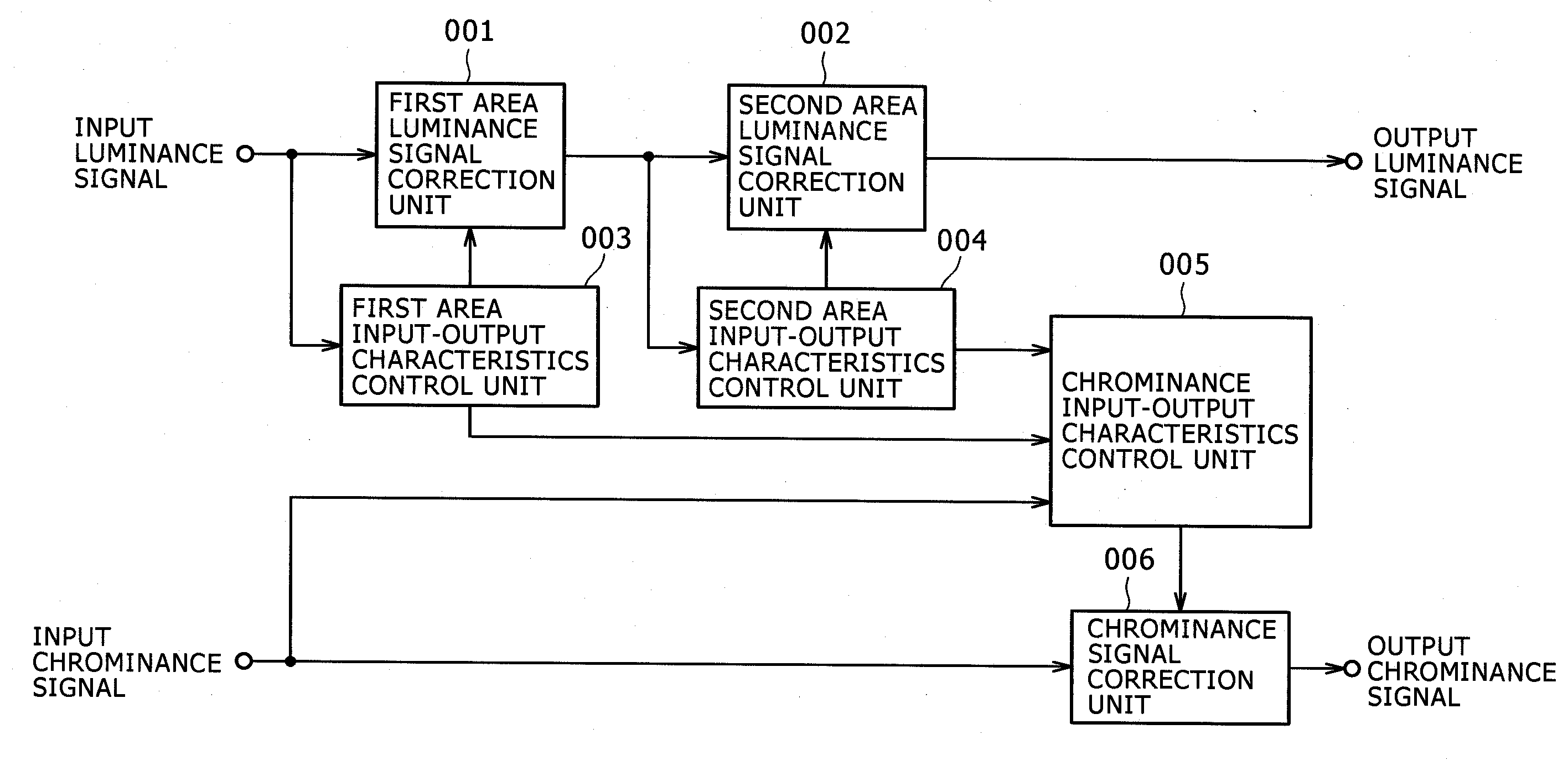
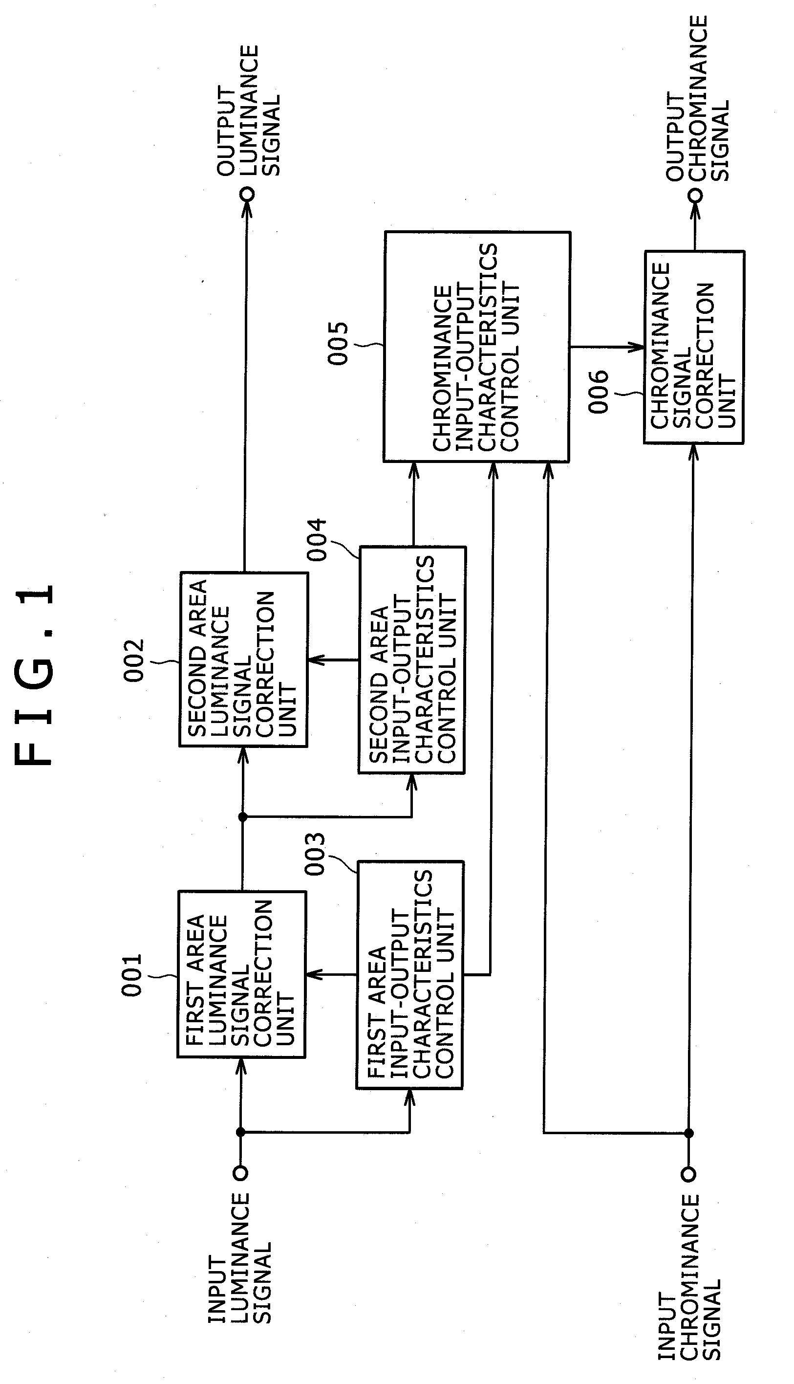
[0036]FIG. 1 illustrates a concept of Embodiment 1 according to the present invention.

[0037]A first area input-output characteristics control unit 003 performs control for changing input-output characteristics in an arbitrary small area of an image, using information on a local area which includes peripheral pixels of the arbitrary small area.

[0038]A first area luminance signal correction unit 001 corrects the input-output characteristics of an input luminance signal for every small area according to an output of the first area input-output characteristics control unit 003.

[0039]FIG. 3 illustrates an example of a concept of the first area unit. The left-hand side of FIG. 3 illustrates an input image which possesses a dark area like blocked-up shadows, a bright area like blown-out highlights, and an ordinary area with originally clear gradation. The right-hand side of FIG. 3 illustrates input-output characteristics for improving contrast of each area.

[0040]On the basis of the informa...

embodiment 2

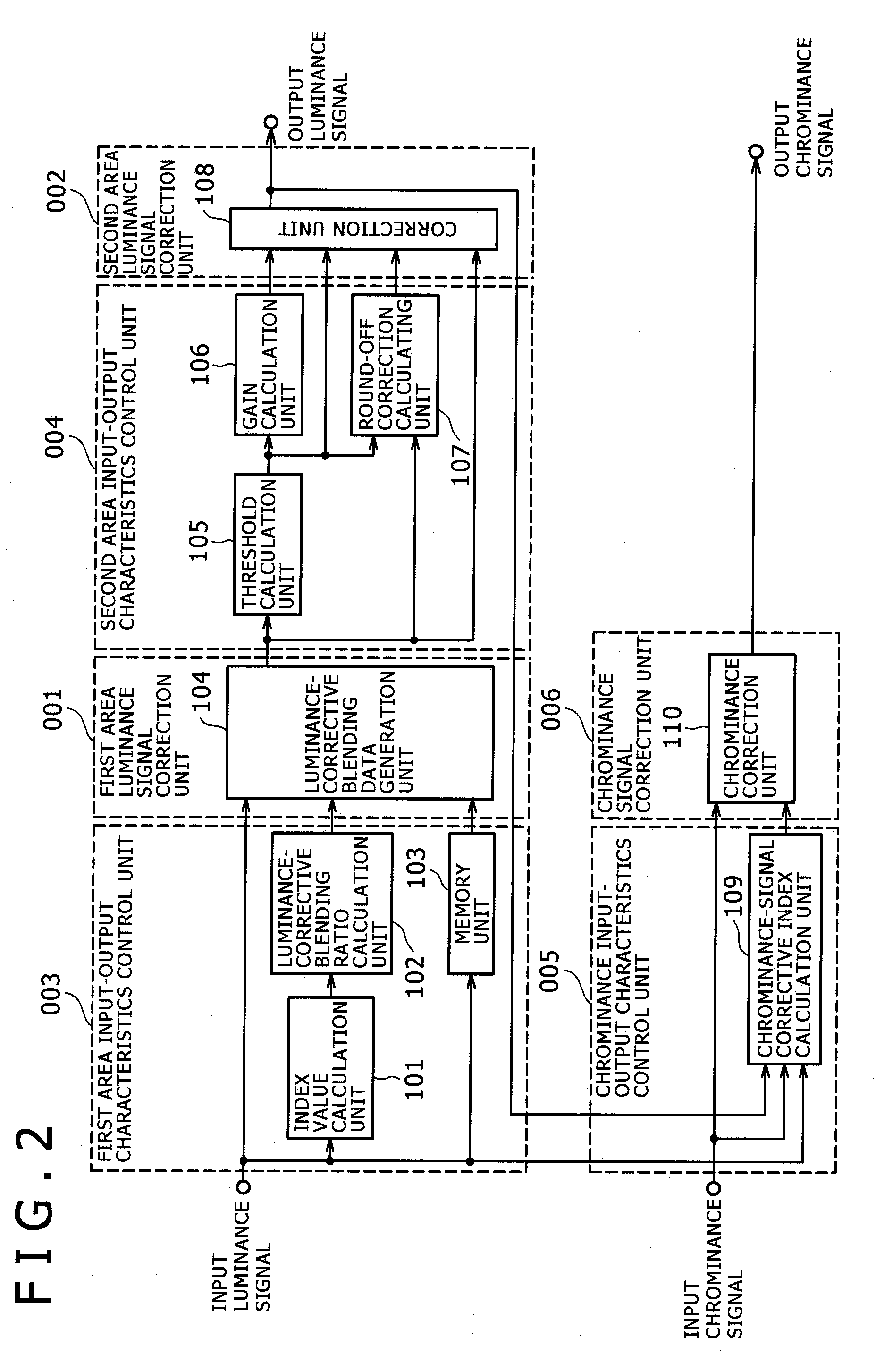
[0048]FIG. 2 illustrates a conceptual diagram of Embodiment 2 according to the present invention.

[0049]An index value calculation unit 101 outputs an index value which is calculated by performing predetermined weighting to a central pixel and its peripheral pixels of an input luminance signal. It is also preferable to assume that the predetermined weighting is to calculate a mean value.

[0050]A luminance-corrective blending ratio calculation unit 102 calculates and outputs a blending ratio with which an output of a memory unit 103 and the input luminance signal are blended.

[0051]FIG. 4 illustrates an example of a blending ratio calculation method for luminance correction. In FIG. 4, a symbol x expresses an index value used as an output of the index value calculation unit 101 (FIG. 2). A symbol x1 expresses a threshold indicative of a low luminance area. A symbol x2 expresses a threshold indicative of a high luminance area. A symbol y1 expresses an intercept of the low luminance area....

embodiment 3

[0070]FIG. 10 illustrates an image signal processing device according to Embodiment 3 of the present invention.

[0071]In FIG. 10, a block 1014 is a first contrast correcting circuit and a block 1015 is a second contrast correcting circuit. A signal flow in FIG. 10 is explained in the following. A representative luminance level of a prescribed area in an input luminance signal is first calculated by a representative luminance calculation circuit 1001, and the input luminance signal is corrected to predetermined characteristics by a luminance signal correction circuit 1002. The input-output characteristics of the luminance signal correction circuit 1002 are described later.

[0072]According to an output of the representative luminance calculation circuit 1001, a rate-of-blending generation circuit 1003 generates a predetermined rate of blending a (0=a=1). An output of the luminance signal correction circuit 1002 is multiplied by (1−a) by a multiplier circuit 1005, and an input luminance ...


PUM


Abstract

The present invention aims at suppressing a noise in a low luminance part and a high luminance part and, at the same time, realizing a high contrast of the parts, and realizing high contrast of a characterizing part of the image as well. The image signal processing is provided with: a first area input-output characteristics control unit which controls change of input-output characteristics for every arbitrary areas, associated with a value of an input luminance signal; a second area input-output characteristics control unit which controls change of input-output characteristics for every arbitrary areas, associated with an output of the first area input-output characteristics control unit; and a chrominance input-output characteristics control unit which controls change of the input-output characteristics of an input chrominance signal, utilizing the output of the first area input-output characteristics control unit and the output of the second area input-output characteristics control unit.

Description

INCORPORATION BY REFERENCE[0001]This application relates to and claims priority from Japanese Patent Application No. 2009-154542 filed on Jun. 30, 2009, the entire disclosure of which is incorporated herein by reference.BACKGROUND OF THE INVENTION[0002](1) Field of the Invention[0003]The present invention relates to an image signal processing device and an image signal processing method.[0004](2) Description of the Related Art[0005]As a related art of the present technical field, there is Japanese Patent Application Laid-Open 2007-318256, for example. The present patent document describes in its abstract of the disclosure as follows: “An image correction circuit capable of easily realizing adaptive color correction taking into account a luminance correction amount is provided. A gamma-correction circuit 21 applies luminance correction (contrast improving) to an input luminance signal Yin. Using an amount of luminance correction ΔY, a chrominance correction unit 3 performs chrominanc...

Claims


Application Information

Patent Timeline
IPC IPC(8): G06K9/00
CPCH04N9/77H04N5/202
Inventor SHIOKAWA, JUNJINONAKA, YUICHIKISANUKI, TAKERU
Owner MAXELL HLDG LTD
Why Eureka
Try Eureka