
Monolithic Laser Cavity

a monolithic solid-state laser and laser cavity technology, applied in semiconductor lasers, laser details, laser output parameters control, etc., can solve the problems of limited harmonic generation efficiency, limited ability to operate at high optical power, limited finesse of adhesive-bearing cavities, etc., to achieve wide optical output power range, efficient harmonic generation, and predictable manufacturing yields of said cavities

Inactive Publication Date: 2013-10-17
WILLIAMSON III ROBERT S +2
View PDF7 Cites 3 Cited by
  • Summary
  • Abstract
  • Description
  • Claims
  • Application Information

AI Technical Summary

Benefits of technology

This patent describes a special laser cavity design that can efficiently generate laser light at different temperatures and powers. It uses a special material called a birefringent crystal which helps to predictably produce light. The cavity is also designed to resist damage from changes in temperature and power. The laser system generates more than 500 mW of green light over a wide temperature range. The technical effects of this patent are a more robust and cost-effective way to generate laser light with a wide range of powers and temperatures.

Problems solved by technology

In practice, cavities relying upon intra-element adhesives have limited finesse and sensitivity to operating temperature, leading therefore to limited harmonic generation efficiency, and limited ability to operate at high optical powers (which generate increased temperatures in the cavity assembly).
Furthermore, adhesive-bearing cavities can have limited finesse due to optical absorption by the adhesive itself.
Cavities that rely upon external mechanical means to hold alignment can be difficult and expensive to manufacture and also are intolerant of external mechanical and thermal stresses, leading to poor or variable performance.
However, such cavities can suffer from limited operating temperature range due to mismatches in the coefficient of thermal expansion (CTE) of the materials in the cavity.
Furthermore, the operating optical power level can be limited by CTE mismatch due to temperature rises within the cavity, most significantly from the gain medium which sustains high intrinsic losses in conversion from the pump laser light to the oscillator light.
If the vanadate crystal is the wrong thickness, or the temperature of the crystal changes (due to ambient conditions or to heat deposited in the crystal itself), the birefringence of the vanadate rotates the 1064 nm oscillator beam and reduces the efficiency of SHG conversion in the KTP crystal.
Because vanadate crystal boules can only be grown in small sizes (typically no more than 30 mm dia×40 mm), it is not cost-effective to polish the crystals to the submicron precision needed.
Very few are able to meet the tight thickness tolerances required for wide operating temperature.
However, this choice of waveplate material places limits on the cavity construction due to a high CTE mismatch between the quartz and other elements of the cavity.
Further, the different index of refraction of the quartz (˜1.5) from the other elements in the cavity (˜1.7 to ˜2.1) necessitates an optical anti-reflection (AR) coating on the surface, which adds cost and complicates many optical bonding techniques.
This type of laser is typically fragile and has many precisely aligned parts, requiring it to be mechanically and thermally isolated by its packaging, leading to large parts and typically high power consumption.
Furthermore, the efficiency and / or output power decreases, sometimes irreversibly, when these lasers are operated in high or low temperature environments.
Monolithic or bonded laser cavities enable “alignment-free” manufacturing and much smaller overall laser sizes, but have historically been limited to 150 mW output power with 10-45° C. operating temperature range at best.
The temperature range is limited by both the ability of the pump laser diode to maintain its wavelength over temperature and by the ability of the non-linear crystals to maintain their performance over temperature.
Specifically, the optical elements in the cavity, notably the vanadate, change their birefringence over temperature, leading to decreased efficiency in conversion of infrared to green light at off-nominal operating temperatures.

Method used


Image

  • Monolithic Laser Cavity
  • Monolithic Laser Cavity
  • Monolithic Laser Cavity

Examples


Embodiment Construction

[0042]It must be noted that as used herein and in the appended documents, the singular forms “a”, “an”, and “the” include plural reference unless the context clearly dictates otherwise. As well, the terms “a” (or “an”), “one or more” and “at least one” can be used interchangeably herein. It is also to be noted that the terms “comprising”, “including”, “characterized by” and “having” can be used interchangeably. All wavelengths are given in units of nanometers unless otherwise noted.

[0043]Unless defined otherwise, all technical and scientific terms used herein have the same meanings as commonly understood by one of ordinary skill in the art to which this invention belongs. All publications and patents specifically mentioned herein are incorporated by reference for all purposes including describing and disclosing the chemicals, instruments, statistical analyses and methodologies which are reported in the publications which might be used in connection with the invention. All references...


PUM


Abstract

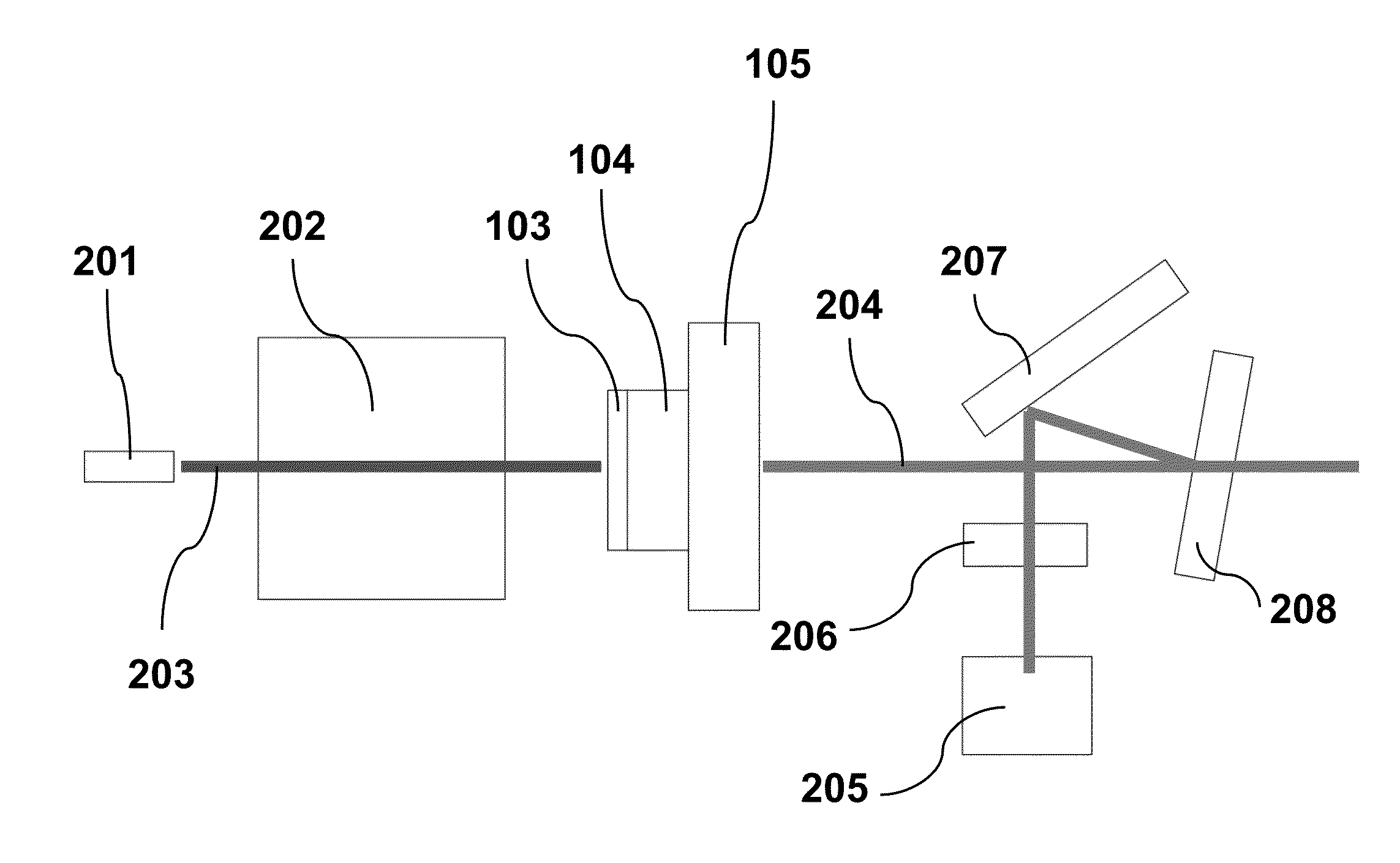
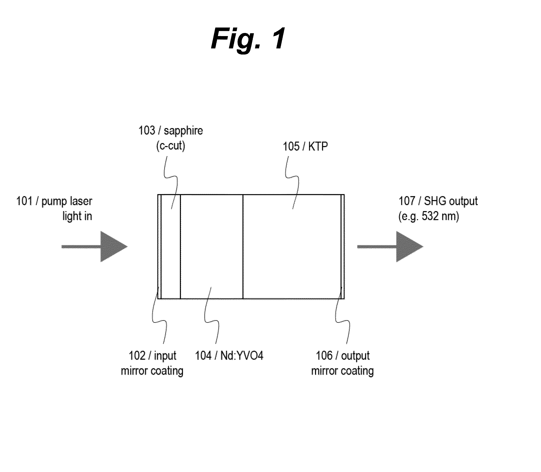
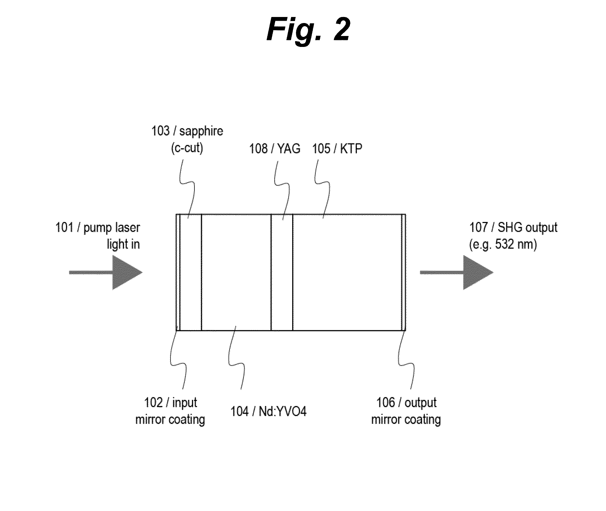
A monolithic laser cavity device includes an input mirror coating, a birefringent crystal quarter waveplate such as sapphire, a birefringent crystal gain medium such as neodymium-doped vanadate, a Type-II second-harmonic-generation crystal such as potassium titanyl phosphate, and an output mirror coating. The optical axes of the Type-II second-harmonic-generation crystal and birefringent crystal gain medium are aligned with each other and aligned 45° relative to the optical axis of the birefringent crystal quarter waveplate.

Description

CROSS-REFERENCE TO RELATED APPLICATIONS[0001]This application claims priority from U.S. Provisional Patent Application 61 / 622595 filed Apr. 11, 2012, which is incorporated herein by reference.FIELD OF THE INVENTION[0002]The present invention relates generally to a laser-diode pumped monolithic solid-state laser devices, and more particularly relates to an intracavity-doubled solid-state laser.BACKGROUND OF THE INVENTION[0003]Solid-state lasers typically rely upon rare-earth-doped crystals to provide the gain element of the laser, and due to the nature of rare earth elements, typically produce invisible infrared radiation (oscillator). In order to produce a wider variety of laser wavelengths, in particular visible wavelengths, a non-linear optical element is introduced into the cavity to double, triple, or quadruple the oscillator frequency, producing a harmonic output wavelength. The non-linear element can be introduced external to the infrared oscillator, or internal to the oscilla...

Claims


Application Information

Patent Timeline
Patent Type & Authority Applications(United States)
IPC IPC(8): H01S5/06
CPCH01S5/0604H01S3/0627H01S3/08054H01S3/08072H01S3/09415H01S3/109H01S3/1611H01S3/1673H01S3/0405
Inventor WILLIAMSON, III, ROBERT S.LU, YAJUNBARTON, DAVID G.
Owner WILLIAMSON III ROBERT S
Learn More