EMI suppressing regulator

Active Publication Date: 2008-07-24
AMI SEMICON BELGIUM
View PDF3 Cites 6 Cited by
  • Summary
  • Abstract
  • Description
  • Claims
  • Application Information

AI Technical Summary

Benefits of technology

[0024]Another aspect of the invention is a corresponding method of regulating power, e.g. a method of regulating a power supply (Vbat) to provide a regulated power supply output (Vout, VDD_core) (e.g. to a varying load, the varying load causing current drain with lower frequency and higher frequency components from the power supply), a regulator circuit being provided having a controllable current source circuit (M1, M2), and a capacitor (Ctank), the method having the steps of receiving the power supply and controlling the controllable current source circuit according to feedback from the regulated power supply output to provide a lower frequency current part of the regulated power supply output, such that the capacitor can supply a higher frequency current part of the regulated power supply output, and controlling the controllable current source circuit to restrict a rate of change of the output of the controllable current source circuit.
[0025]Another aspect of the invention is a method of manufacturing a regulator circuit, e.g. a method of manufacturing the integrated circuit having power control and logic circuitry, and a regulator circuit, the regulator circuit

Problems solved by technology

Without a proper design, EMC of integrated circuits will become a limiting factor in the performance of every advanced electronic system.
However, due to more sizable wires forming antennas and to more rapidly changing currents, the current variation (di/dt) in power supply lines generates most of the noise radiation emitted.
It is also known from U.S. Pat. No. 6,

Method used


Image

  • EMI suppressing regulator
  • EMI suppressing regulator
  • EMI suppressing regulator

Examples


embodiment

of FIG. 1

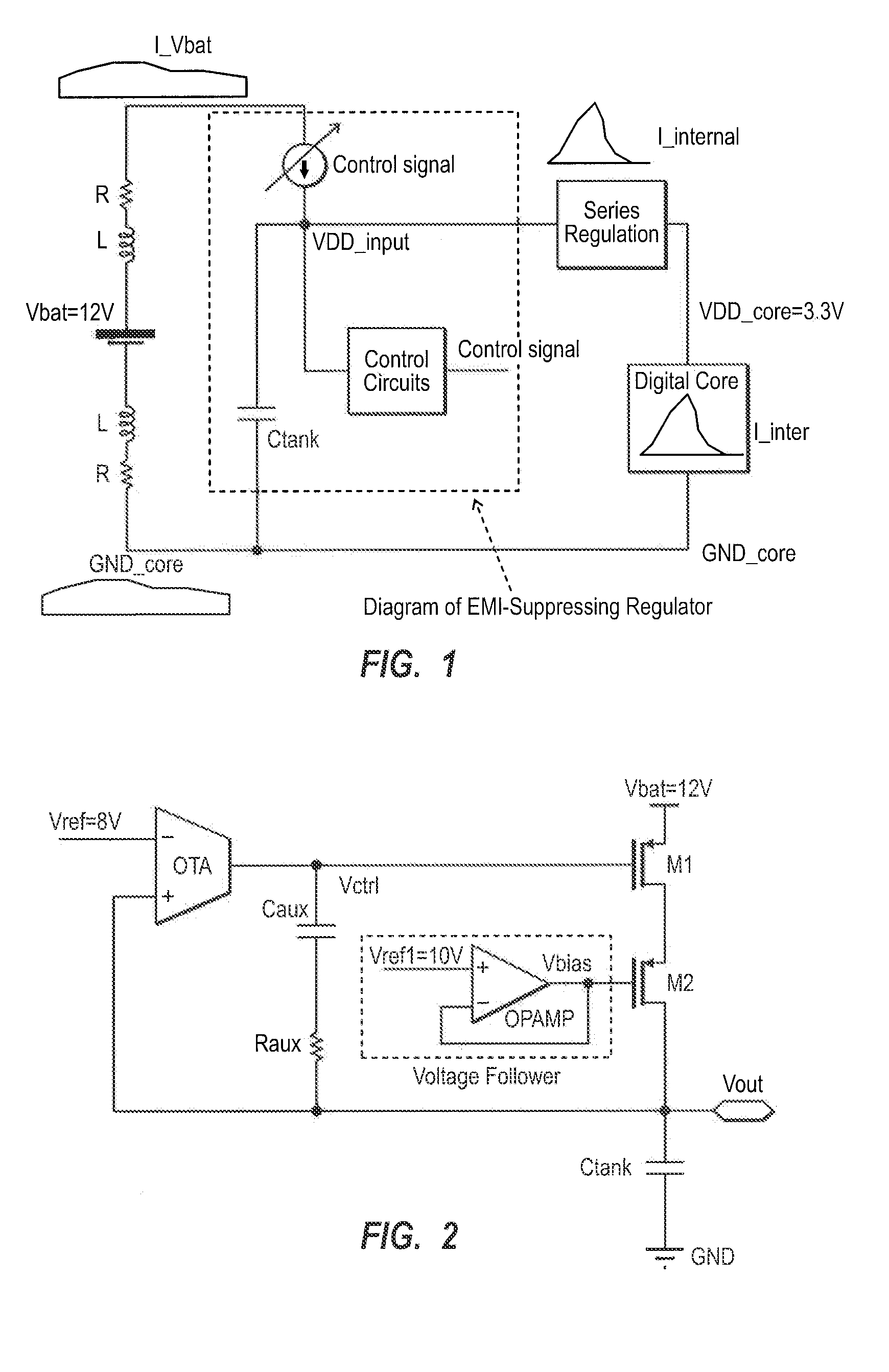
[0040]A first embodiment of the invention is illustrated in schematic form in FIG. 1. The inventors recognised that for low noise digital cells, using a current source can provide a major di / dt reduction, and that slower variations of current provides better EMC performance. Furthermore minimizing the static power consumption is useful for practical applications. To achieve a smarter way of controlling how current is delivered to the internal digital cores, a circuit according to a first embodiment is shown in FIG. 1. This shows a battery to represent a power source schematically with an associated resistance and inductance R,L. In general the power source could be any DC power supply source e.g. a dynamo, a fuel cell, a photovoltaic cell, etc. This power source can be remote from the regulator circuit, in which case, the power supply lines to the regulator can be long enough to act as an antenna and can radiate EMI depending on an amount of current and a rate of change of ...


PUM


Abstract

A regulator circuit receives a power supply and provides a regulated power supply output suitable for integrated circuitry. It has a controllable current source circuit, a controller and a capacitor, such that an output of the controllable current source circuit can provide a lower frequency current part of the regulated power supply output, and the capacitor can supply a higher frequency current part of the regulated power supply output. The controllable current source circuit is controlled according to feedback from the regulated power supply output, and to restrict a rate of change of the output of the controllable current source circuit. The amount of EMI noise caused by high rate of change of current in power supply lines to the regulator circuit can be reduced. This can be done more efficiently or using a smaller capacitor than known arrangements.

Description

CROSS-REFERENCE TO RELATED APPLICATIONS[0001]This patent application claims the benefit of British Patent Application Serial No. 0700407.0, filed Jan. 10, 2007, which patent application is incorporated herein by reference in its entirety.FIELD OF THE INVENTION[0002]This invention relates to regulator circuits, to integrated circuits having such regulator circuits, to methods of manufacturing the same, and methods of regulating power supplies.BACKGROUND[0003]In many technical fields EMI (electromagnetic interference) is a constraint. For example in automotive vehicles, the electromagnetic environment generated by devices like ABS braking systems, airbag sensors, or engine management, is omnipresent. Hence, EMC (electromagnetic compatibility) is of great importance to safety. Without a proper design, EMC of integrated circuits will become a limiting factor in the performance of every advanced electronic system. However, due to more sizable wires forming antennas and to more rapidly ch...

Claims


Application Information

Patent Timeline
IPC IPC(8): G05F1/565
CPCG05F1/56
Inventor ZHOU, JUNFENGDEHAENE, WIM
Owner AMI SEMICON BELGIUM
Why Eureka
Try Eureka