
Chemical process accelerator systems utilizing taylor vortex flows

a technology of accelerator system and vortex flow, which is applied in the direction of physical/chemical process catalyst, gas-gas reaction process, cell components, etc., can solve the problems of significant improvement in fuel cell performance, inability to replicate the operating conditions of chemical reactor, and trade-off between transport-limited and surface-limited, so as to reduce the surface-limiting and transport-limiting characteristics of catalysts, reduce the effect of surface-limiting and surface-limiting of catalytic reactions

Active Publication Date: 2010-12-30
GLOBAL ENERGY SCI CALIFORNIA
View PDF14 Cites 12 Cited by
  • Summary
  • Abstract
  • Description
  • Claims
  • Application Information

AI Technical Summary

Benefits of technology

[0022]generating high-shear-rate laminar CCF at catalyst surfaces for accelerating mass transport of reactants,
[0027]f) eliminating those degrading reaction products from the reactors.When used in combination with catalysts—especially those optimized for use in or with TVF and laminar CCF, reactions rates and extraction efficiencies well beyond those taught by the prior art can be achieved.
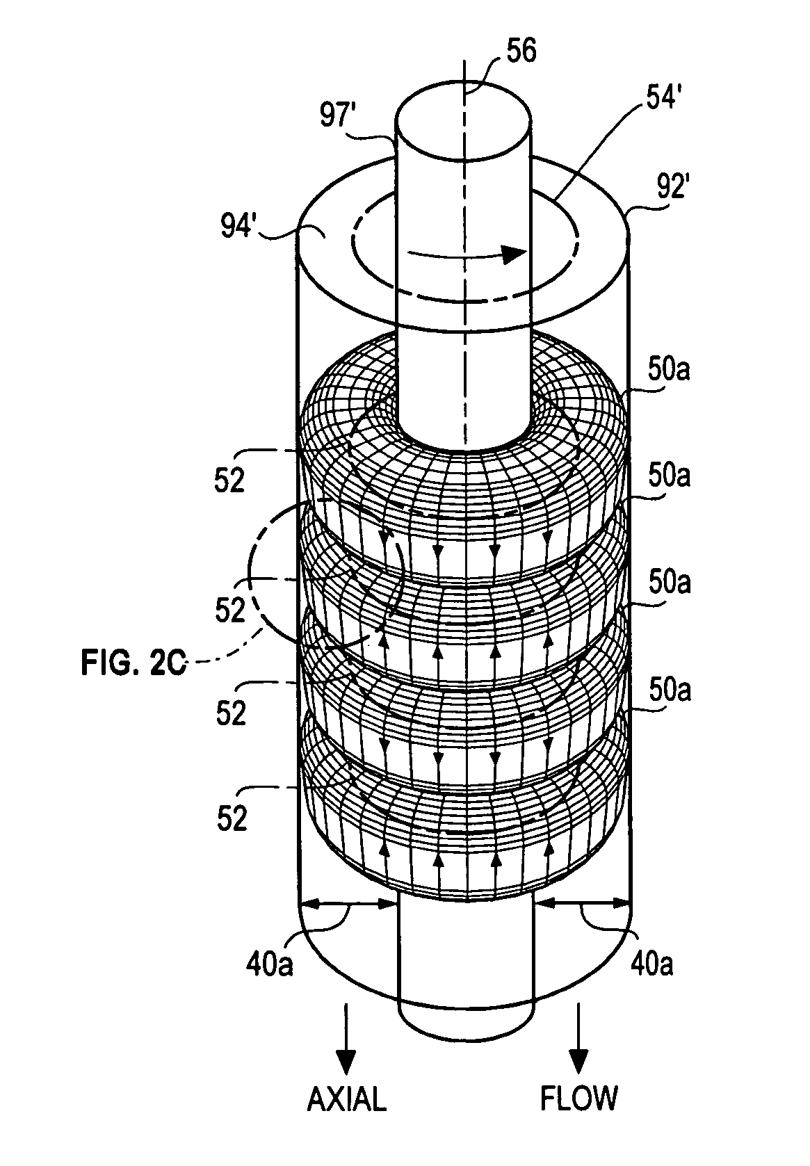
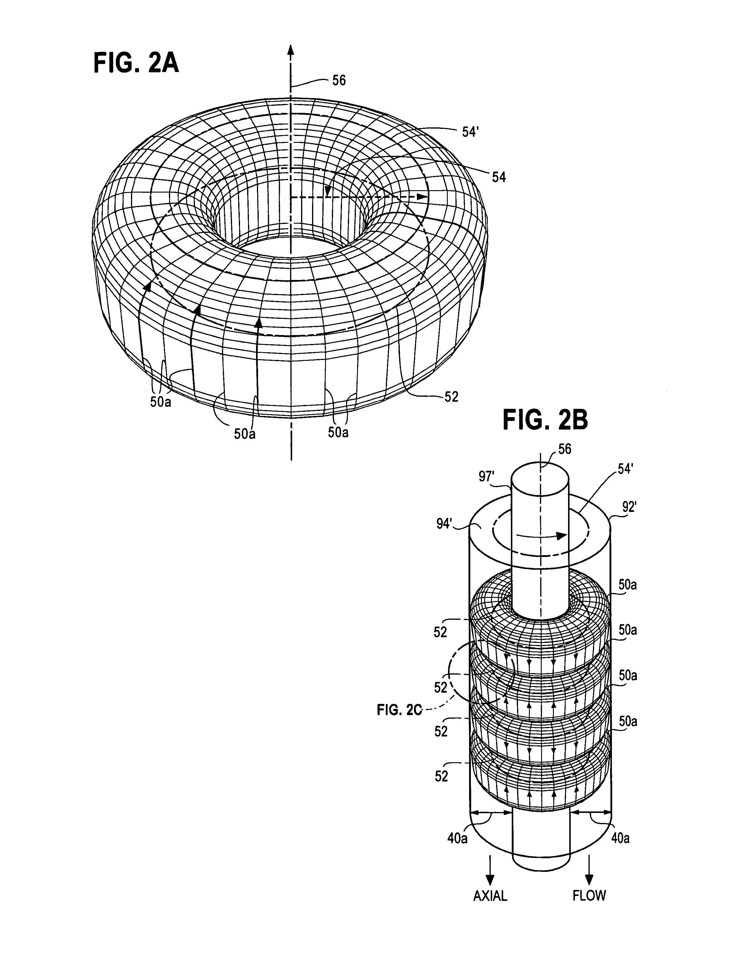
[0047]The present invention is a chemical process accelerator system comprising robust catalyst compositions in which viscid fuel, electrolyte or other chemical fluids pass between relatively rotating, cylindrical surfaces that cause TVF and high-shear-rate laminar CCF within the fluids to reduce both transport-limiting and surface-limiting of catalytic reactions. In addition, TVF facilitate removal of contaminants that could damage chemical reactors, chemical cells or catalysts.
[0048]It is therefore a first object of the present invention to provide robust chemical process accelerator systems comprising catalysts and TVF that are optimized for use in chemical reactors for reducing surface-limiting and transport-limiting characteristics of the catalysts.
[0050]A third object of this invention is to provide catalysts, TVF and CCF that rapidly remove intermediate products from catalyst surfaces to increase reaction rates in chemical reactors.
[0053]A sixth object of this invention is to provide chemical process accelerator systems that bring reactant chemicals to catalyst particle surfaces in high-shear-rate laminar flows having dimensions in the range of 2-5 nanometers, exchange intermediate reactants and then carry away ions, intermediate reaction products, fluids (e.g. water) or solids (e.g. carbon) that could reduce reaction rates or poison the catalyst particle surfaces with little delay.

Problems solved by technology

Although the prior art technologists consider catalysts as the most prominent constituents and they garner an overwhelming share of research investigation, catalysts are only one component of chemical process accelerator systems needed to achieve commercially viable reaction rates.
For example, prior art fuel cell catalysts have yet to break a longstanding barrier that will enable fuel cell electrodes to generate more than 1-Ampere per cm2 of electrode surface area over a long operating life without being poisoned by reactants or corroding to the point of uselessness.
In the case of electrochemical cells—and more specifically fuel cells, extensive research is now being conducted with half-cell analyses of a wide variety of catalysts; however, there is yet to be any significant improvement in fuel cell performance.
Because SHE and RHE half cell experiments are usually run at or near room temperature, at pressures of about 1-bar and with little or no fluid flow, they cannot replicate operating conditions in chemical reactors, such as fuel cells, where these parameters and intermediate reaction products will most certainly be different.
Transport-limiting occurs because reactants are impeded in reaching or leaving catalyst sites.
Surface-limiting occurs because of a tradeoff between the sum of reaction energies from primary and intermediate chemicals, surface attraction of ions such as H+ and OH− and poisoning rates by reaction products, such as CO.
In addition, there can be tradeoffs between transport-limited and surface-limited factors, such as how changes in flow rates and pressures that promote chemicals moving to or from catalyst sites can change concentrations of intermediate chemicals capable of adhering to the catalyst surfaces, poisoning catalysts or, at least, retarding reactions.

Method used


Image

  • Chemical process accelerator systems utilizing taylor vortex flows
  • Chemical process accelerator systems utilizing taylor vortex flows
  • Chemical process accelerator systems utilizing taylor vortex flows

Examples


Embodiment Construction

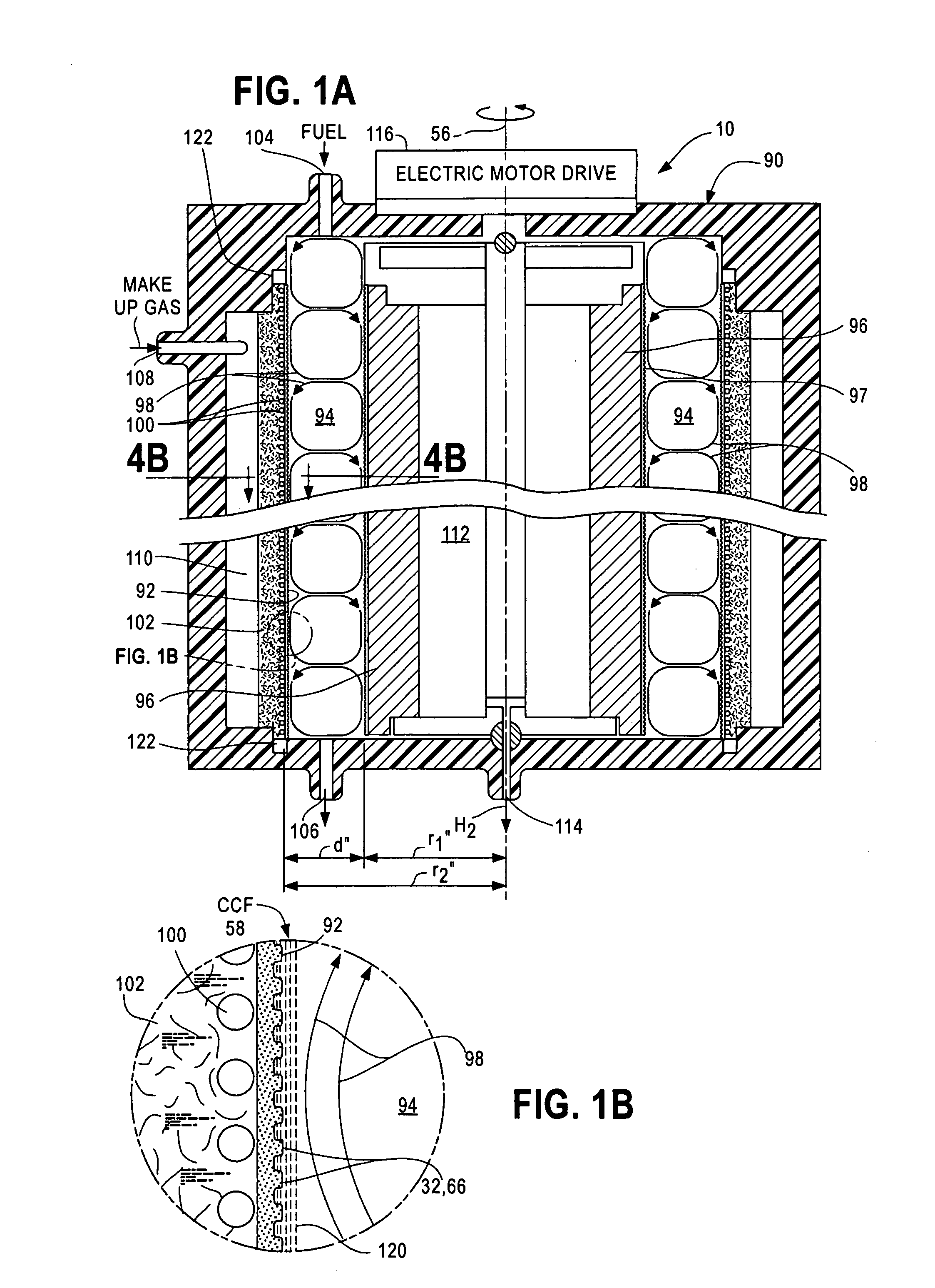
[0071]A chemical processor accelerator system 10 comprises two principal components; namely, Taylor Vortex Flows (TVF) that generate high-shear-rate laminar Circular Couette Flows (CCF) and catalysts. While these components cooperate to promote chemical reactions in a wide variety of chemical reactors, each will be described separately in an embodiment taught in Case B, which discloses a fuel reformer used to extract H2 from fuels. To assist the reader, element numbers of FIG. 1A and FIG. 1B used in the following description of the fuel reformer are the almost the same as those used in FIG. 5A and FIG. 5B of Case B.

[0072]FIG. 1A and FIG. 1B are cross-sectional views of portions of an external TVF fuel reformer 90 suitable for a) pyrolytic or b) steam or partial oxidation reforming of hydrocarbon fuels such as methane (CH4), methanol (CH3OH), ethanol (C2H5OH), propane (C3H8), butane (C4H10), octane (C8H18), kerosene (C12H26) and gasoline as well as other hydrogen-bearing chemicals su...


PUM

PropertyMeasurementUnit
Temperatureaaaaaaaaaa
Massaaaaaaaaaa

Abstract

Chemical process accelerator systems comprising viscid fluid Taylor Vortex Flows (98, 50a) with high-shear-rate laminar Circular Couette Flows (58) in contact with catalysts (92, 92′, 30, 32, 32f, 32g, 36, 40, 44, 45, 46, 47, 48), catalytic compositions and structures in chemical reactors and electrochemical cells (e.g. fuel cells, fuel reformers) are disclosed.

Description

CROSS-REFERENCE TO RELATED APPLICATIONS[0001]This application claims the benefit of U.S. Provisional Application No. 61 / 220,583 filed 26 JUN. 2009 by Halbert P. Fischel, which is incorporated herein by reference.[0002]This application, identified as Case C, is related to my following applications:[0003]Case A: Electrochemical Cells Utilizing Taylor Vortex Flows, application Ser. No. ______;[0004]Case B: Fuel Reformers Utilizing Taylor Vortex Flows, application Ser. No. ______;[0005]Case D: Direct Reaction Fuel Cells Utilizing Taylor Vortex Flows, application Ser. No. ______; and[0006]Case E: Dynamic Accelerated Reaction Batteries Utilizing Taylor Vortex Flows, filed application Ser. No. ______ with Philip Michael Lubin and Daniel Timothy Lubin.[0007]Case A, Case B, Case C (this case), Case D and Case E were all filed on the same day. All of these applications have been assigned to the same assignee. The other applications are incorporated herein by reference.STATEMENT REGARDING FEDE...

Claims


Application Information

Patent Timeline
IPC IPC(8): B01J8/14B01J19/00
CPCB01F7/008Y02E60/522B01J12/007B01J14/005B01J15/005B01J16/005B01J19/1806B01J19/1893B01J2219/00083B01J2219/00135C01B3/065C01B3/40C01B2203/0233C01B2203/0261C01B2203/0277C01B2203/0283C01B2203/066C01B2203/1041C01B2203/1047C01B2203/1064C01B2203/107C01B2203/1076C01B2203/1082C01B2203/1223C01B2203/1229C01B2203/1241C01B2203/1247H01M4/90H01M4/92Y02E60/362Y02E60/523Y02E60/50B01J10/007Y02P20/52Y02E60/36B01F27/272
Inventor FISCHEL, HALBERT
Owner GLOBAL ENERGY SCI CALIFORNIA
Learn More