Photoacoustic imaging apparatus and photoacoustic imaging method

a technology of photoacoustic imaging and equipment, applied in the field of photoacoustic imaging equipment and photoacoustic imaging method, can solve the problem of large image deterioration

Inactive Publication Date: 2010-12-30
CANON KK
View PDF15 Cites 38 Cited by
  • Summary
  • Abstract
  • Description
  • Claims
  • Application Information

AI Technical Summary

Benefits of technology

[0017]According to the present invention, by reconstructing an image without the use of the differential value of a detection signal, it is possible to reconstruct the image closer to an actual acoustic wave generation source distribution even under a condition that is not ideal, including noise, etc.

Problems solved by technology

The following are basically raised as main causes of image deterioration: (1) the band limitation of the acoustic wave detector (incapability of dealing with acoustic waves of all frequencies); (2) the device element width of the acoustic wave detector; (3) the limited view; and (4) noise.
In particular, in the UBP method, a value proportional to the differential value of the detection signal is made use of as projection data, as shown in equation (7), so it is greatly affected by the influence of noise, etc., and an image obtained deteriorates to a large extent.

Method used


Image

  • Photoacoustic imaging apparatus and photoacoustic imaging method
  • Photoacoustic imaging apparatus and photoacoustic imaging method
  • Photoacoustic imaging apparatus and photoacoustic imaging method

Examples


Embodiment Construction

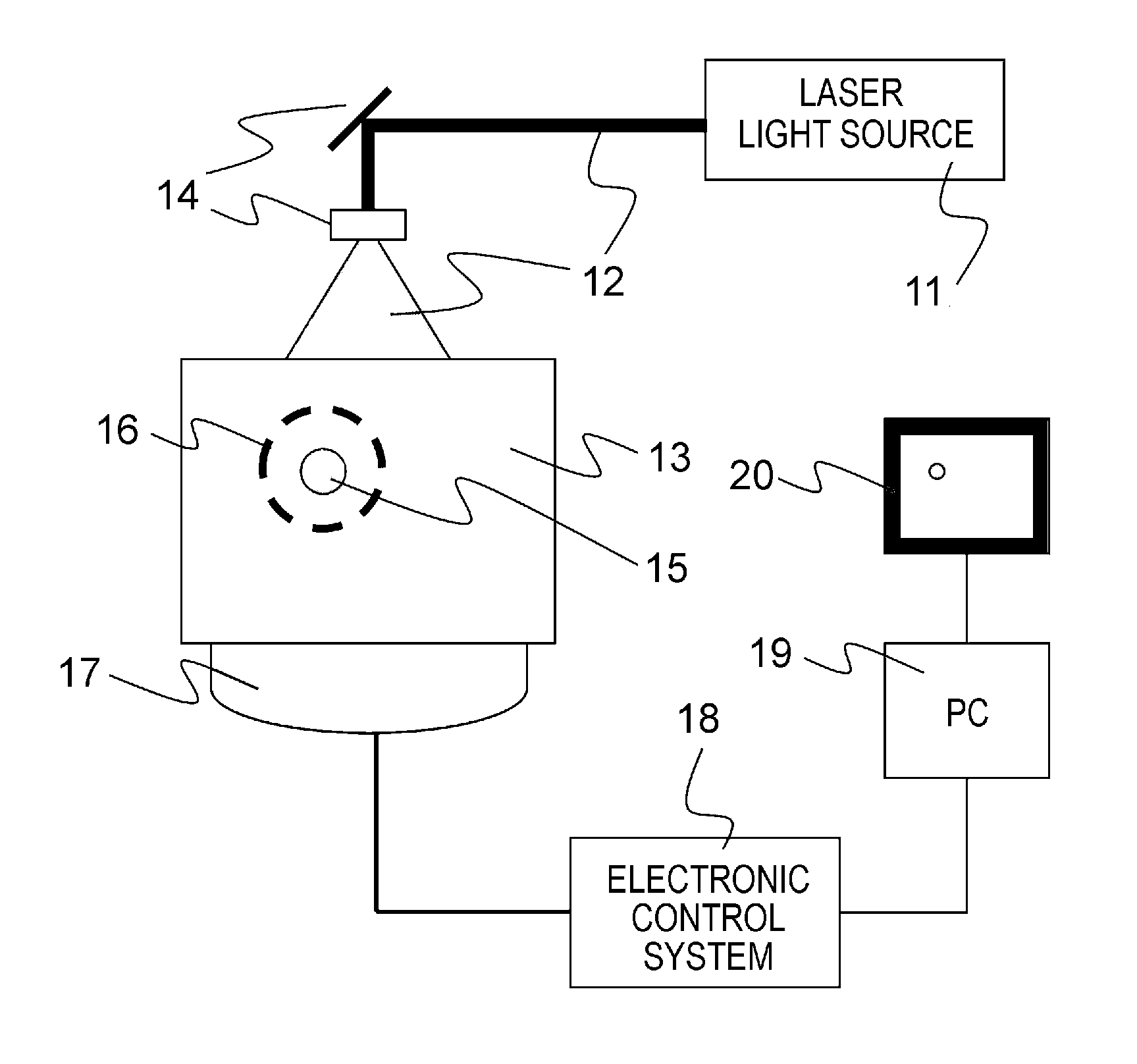
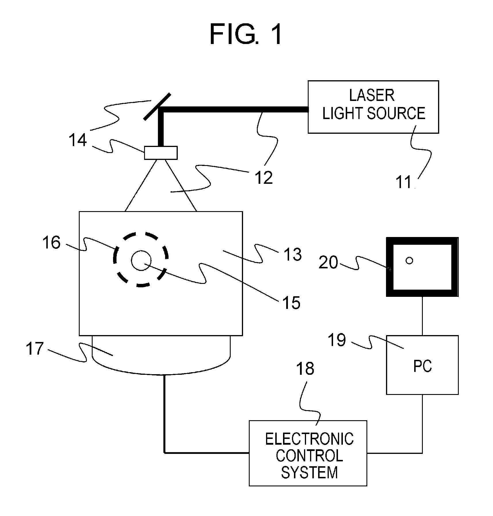
[0023]Hereinafter, reference will be made to a preferred embodiment of the present invention, while referring to the accompanying drawings. FIG. 1 shows an example of the construction of a photoacoustic imaging apparatus to which a photoacoustic imaging method of the present invention can be applied. The photoacoustic imaging apparatus is to make it possible to image biological information for the purposes of diagnosing malignant tumors, blood vessel diseases, etc., observing the progress of a chemical treatment, etc. In the present invention, biological information is a source distribution of an acoustic wave produced by light irradiation, which includes an initial pressure distribution in a living body or an optical energy absorption density distribution derived therefrom, and a concentration distribution of the substances which constitute a living body (biological) tissue, obtained from those pieces of information. For example, the concentration distribution of substances is the ...


PUM


Abstract

A photoacoustic wave detector detects a photoacoustic wave generated inside a specimen by light irradiated thereto. A signal processing device: forms first volume data from a first signal, the first signal being the detection signal acquired from the detector or a signal obtained by adjusting an amplitude of the detection signal; forms second volume data from a second signal, the second signal being a signal obtained by changing a phase of the first signal; forms third volume data from the first and second volume data; and generates and outputs image data representing information on an interior of the specimen from the third volume data.

Description

BACKGROUND OF THE INVENTION[0001]1. Field of the Invention[0002]The present invention relates to a photoacoustic imaging method used in a photoacoustic imaging apparatus.[0003]2. Description of the Related Art[0004]The study of an optical imaging apparatus for obtaining information inside a specimen such as a living body by using the light irradiated from a light source such as a laser is actively advanced in medical fields. As one of such optical imaging techniques, there has been proposed photoacoustic tomography (PAT). The photoacoustic tomography is a technique in which acoustic waves generated from a living body (biological) tissue, which has absorbed the energy of light propagated and diffused in the interior of a specimen, are detected at a plurality of locations surrounding the specimen, so that the signals thus obtained are subjected to mathematical analysis processing to visualize the information related to optical property values in the interior of the specimen. As a resu...

Claims


Application Information

Patent Timeline
Patent Type & Authority Applications(United States)
IPC IPC(8): A61B5/05
CPCA61B5/0059G01N21/1702A61B5/0095A61B5/0073
Inventor FUKUTANI, KAZUHIKONAKAJIMA, TAKAO
Owner CANON KK
Why Eureka
Try Eureka