Posterior Dynamic Stabilization Device Having A Mobile Anchor

a dynamic stabilization device and mobile technology, applied in the field of posterior dynamic stabilization devices, can solve the problems of further damage, limited use of caps, and disadvantages of caps, and achieve the effects of less translational motion, less translational motion, and less overload of adjacent levels

Active Publication Date: 2010-12-30
DEPUY SYNTHES PROD INC
View PDF136 Cites 26 Cited by
  • Summary
  • Abstract
  • Description
  • Claims
  • Application Information

AI Technical Summary

Benefits of technology

[0018]The present invention provides a PDS device that allows predetermined and prescribed interpedicular motion. It is the understanding of the present inventor that this is the first PDS device of its kind to limit such motion by displacement of a mobile element (and not by load upon a static element). The PDS device of the present invention can also be made to be compatible with minimally invasive surgery (MIS) techniques. It allows the use of traditional pedicle screw-rod placement techniques in a flexible system, thereby enabling many different treatment options, using components that are familiar to the surgeon. The PDS device of the present invention intends to preserve desirable amounts of physiologic motion and can be used on multiple levels (especially to top off), to transition loads by limiting displacements.
[0019]The present invention contemplates a PDS device for motion applications. In this sense, it is different than certain motion devices used in scoliosis applications, such as those of Martin and Rivard, in which the device allows growth and limited motion along the longitudinal axis of the rod. Whereas Martin and Rivard contemplate a correcting scoliosis rod, the present invention contemplates mobile anchor PDS systems for treating stenosis, degenerative spondylolisthesis, and degenerative disc disease. In topping off applications, the present invention can be used as a protection device adjacent to a fusion to prevent overloading of the healthy discs. In some instances the device may be used at more than one level, thereby allowing the device to absorb some of the load and prevent adjacent disc disease.
[0026]The present invention allows desirable amounts of physiologic flexion, extension, lateral bending and axial rotation to be set by the surgeon after iatrogenic instability. The limited range of motion realized by the present invention is advantageous in certain PDS indications, such as topping-off fusions, stenosis, and degenerative spondylolisthesis.
[0028]One embodiment of the present invention allows the extent of anchor translation within the system to be dictated by the flexibility of the rod to which it is attached. The ability of the mobile anchor to slide on the rod will be dictated by the inherent flexibility of the rod. In these cases, a flexible rod will be expected to produce more translational motion, while a rigid rod would be expected to allow less translational motion.
[0029]The system of the present invention allows both the anchors and stops to be positioned at adjacent levels to limit motion, such that the loads can be effectively transitioned from one level to the next when topping off. This transitioning allows a motion gradient to be achieved to minimize overloads of adjacent levels. Because it beneficially provides physiologic displacements at adjacent levels, the present invention potentially beneficially reduces both the incidence of adjacent disc disease and the necessity of subsequent fusion procedures.

Problems solved by technology

As a result, additional stress may be applied to the adjoining levels, thereby potentially leading to further damage.
Capping techniques, however, are limited in use as they will not remove the source of the pain in osteoarthritic joints.
Caps are also disadvantageous as they must be available in a variety of sizes and shapes to accommodate the wide variability in the anatomical morphology of the facets.
Caps also have a tendency to loosen over time, potentially resulting in additional damage to the joint and / or the bone support structure containing the cap.
One drawback of current articulating facet replacement devices, however, is that they require the facet joints to be resected.
Moreover, alignment of the articulating surfaces with one another can be challenging.
Traditional spine fusion may result in early degeneration at adjacent spine levels due to increased loading and compensation.
This may result in subsequent surgeries to fuse additional levels.

Method used


Image

  • Posterior Dynamic Stabilization Device Having A Mobile Anchor
  • Posterior Dynamic Stabilization Device Having A Mobile Anchor
  • Posterior Dynamic Stabilization Device Having A Mobile Anchor

Examples


Embodiment Construction

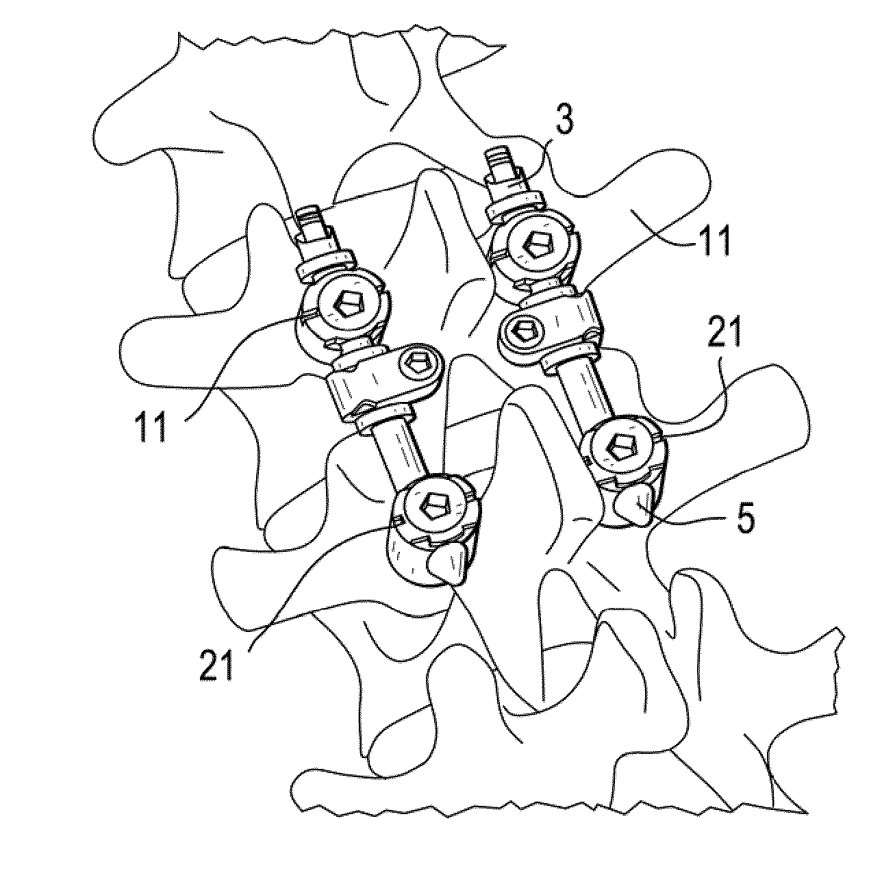
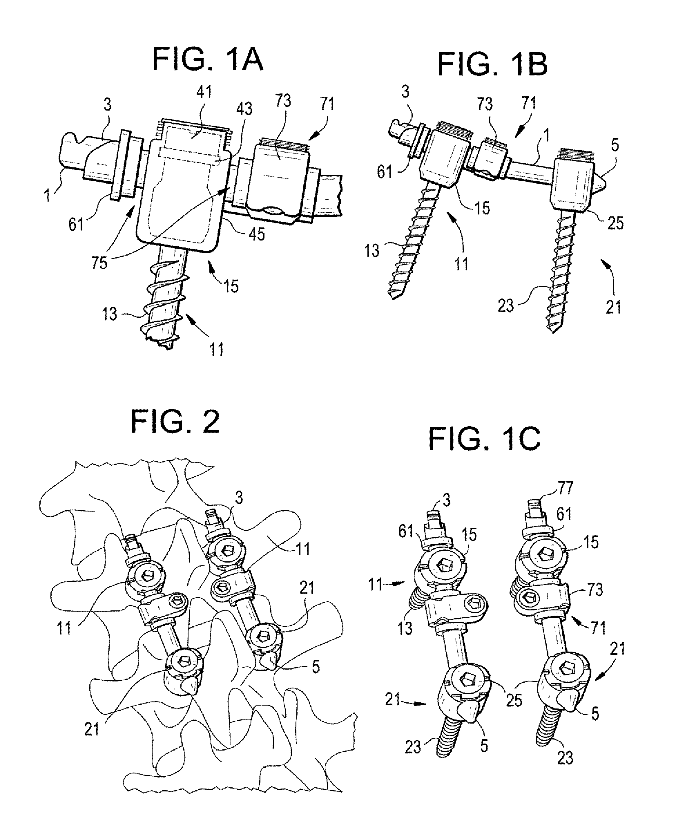
[0060]Now referring to FIGS. 1a-1c, in one preferred embodiment of the invention, there is provided a posterior dynamic spinal stabilization system, comprising:[0061]a) a spinal rod 1 having a first end 3 used as a guide for a mobile anchor and a second end 5,[0062]b) a mobile anchor 11 having i) a shank 13 and ii) a rod-receiving portion 15 containing a bearing insert 45(or “bearing”) adapted to mate to the first end of the rod and the head of the shank, thereby enabling translation along the rod and pivoting about the rod,[0063]c) a fixed anchor 21 having i) a shank 23 and ii) a rod-receiving portion 25 adapted to lock to the second end of the rod.[0064]d) a first motion-limiting stop 61 positioned on the rod at a location superior to the mobile anchor, and[0065]e) a second motion-limiting stop 71 positioned on the rod at a location inferior to the mobile anchor and comprising a polymeric bumper 73.

[0066]Now referring to FIG. 1a, gaps 75 are provided along the rod between the stop...


PUM


Abstract

A posterior dynamic spinal stabilization device utilizing a spinal rod, a fixed anchor, a mobile anchor adapted for both translation and pivoting, a mobile anchor-limiting stop affixed to the rod and an optional bumper-type, a rod with at least one limiting stop. It allows predetermined and prescribed interpedicular motion. It allows the use of traditional pedicle screw-rod placement techniques in a flexible system possessing many treatment options using familiar components that are familiar to the surgeon, and can be used on multiple levels (especially to top off) and can transition loads by limiting displacements.

Description

CONTINUING DATA[0001]This patent application claims priority from pending U.S. Provisional Patent Application No. 61 / 220,341, filed Jun. 25, 2009, entitled “Posterior Dynamic Stabilization Device Having a Mobile Anchor” (DEP-6238USPSP), the specification of which is incorporated by reference in its entirety.BACKGROUND OF THE INVENTION[0002]The vertebrae in a patient's spinal column are linked to one another by the disc and the facet joints, which control movement of the vertebrae relative to one another. Each vertebra has a pair of articulating surfaces located on the left side, and a pair of articulating surfaces located on the right side, and each pair includes a superior articular surface, which faces upward, and an inferior articular surface, which faces downward. Together the superior and inferior articular surfaces of adjacent vertebra form a facet joint. Facet joints are synovial joints, which means that each joint is surrounded by a capsule of connective tissue and produces ...

Claims


Application Information

Patent Timeline
Patent Type & Authority Applications(United States)
IPC IPC(8): A61B17/70A61B17/86A61B17/88
CPCA61B17/7005A61B17/7008A61B17/7046A61B17/7035A61B17/7037A61B17/702
Inventor FANGER, JONATHANMOUMENE, MISSOUM
Owner DEPUY SYNTHES PROD INC
Why Eureka
Try Eureka