Automatic correction of past position errors for location and inventory tracking

a technology for location and inventory tracking, applied in surveying, navigation, instruments, etc., can solve the problems of not having the capability to improve the accuracy of previous position estimates, and the system and method of the present application are also differen

Active Publication Date: 2010-12-30
MI JACK PRODS
View PDF12 Cites 78 Cited by
  • Summary
  • Abstract
  • Description
  • Claims
  • Application Information

AI Technical Summary

Benefits of technology

[0023]In embodiments where the real-time position estimates include confidence levels, the confidence levels are used in the generation of the calibrated past traj

Problems solved by technology

Since the prior art methods are designed to improve the accuracy of the current position estimate using history data, they do not have the capability to improve the accuracy of previous position estimates.
As a result, t

Method used


Image

  • Automatic correction of past position errors for location and inventory tracking
  • Automatic correction of past position errors for location and inventory tracking
  • Automatic correction of past position errors for location and inventory tracking

Examples


first embodiment

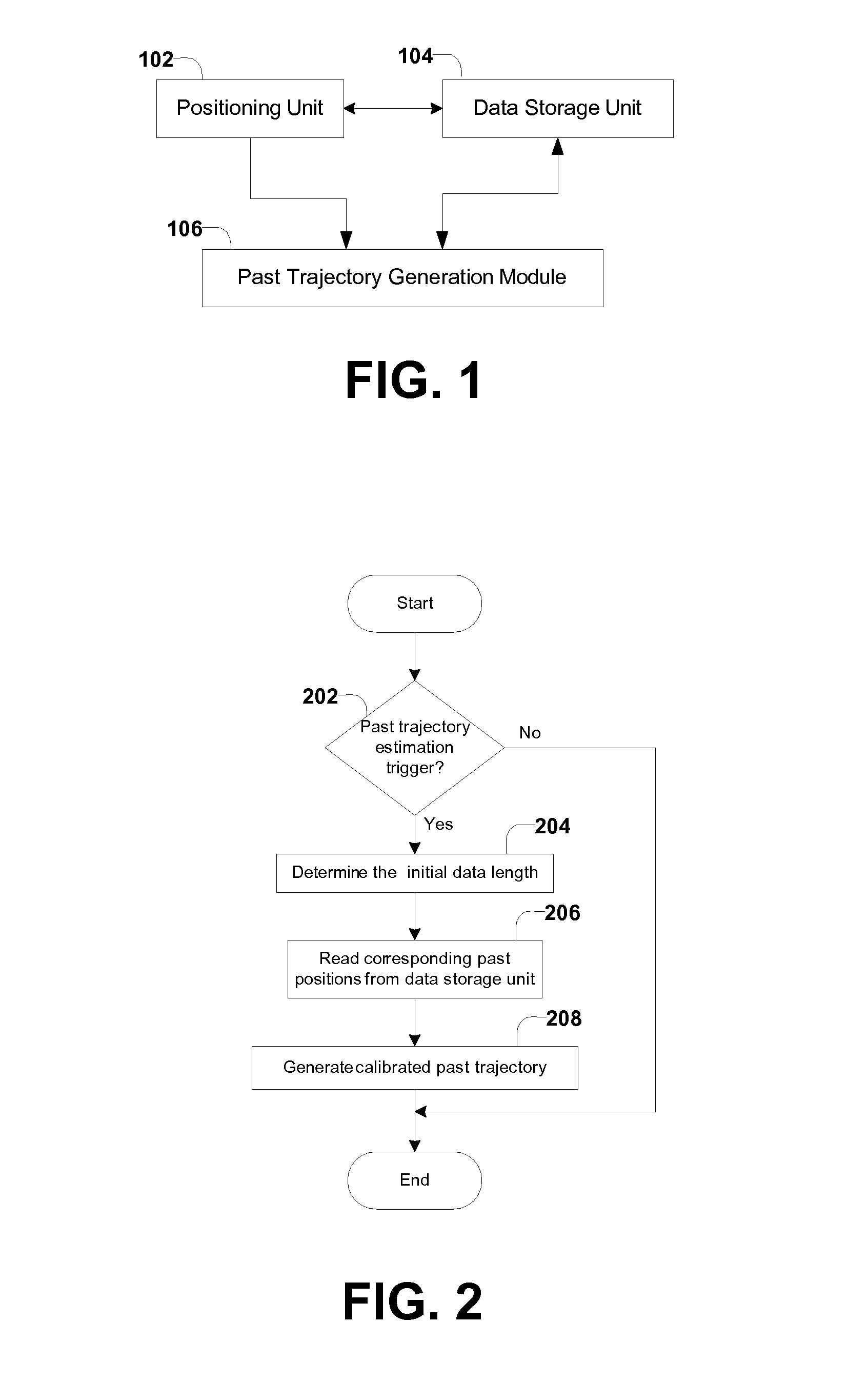
[0047]FIG. 1 shows the system configuration of the position tracking system. In this embodiment, the position tracking system includes a positioning unit 102, a data storage unit 104, and a past trajectory generation module 106.

[0048]The positioning unit 102 provides real-time position estimates of a mobile object, where the real-time position estimates are determined based on the measurements up to the time that these position data are referenced. The positioning unit 102 can include but is not limited to the following positioning sensors: a single GPS or DGPS, an INS, motion sensors such as yaw rate sensor and / or speed sensor, cameras, radar and LIDAR. The positioning unit 102 could be installed on the mobile object (e.g., when GPS or DGPS, INS, or motion sensors are used), or it could be outside or away from the mobile object (e.g., when cameras, radars, LIDARs, or RTLS are used). The processing techniques involved in such a positioning unit include tightly-coupled GPS / INS integr...

second embodiment

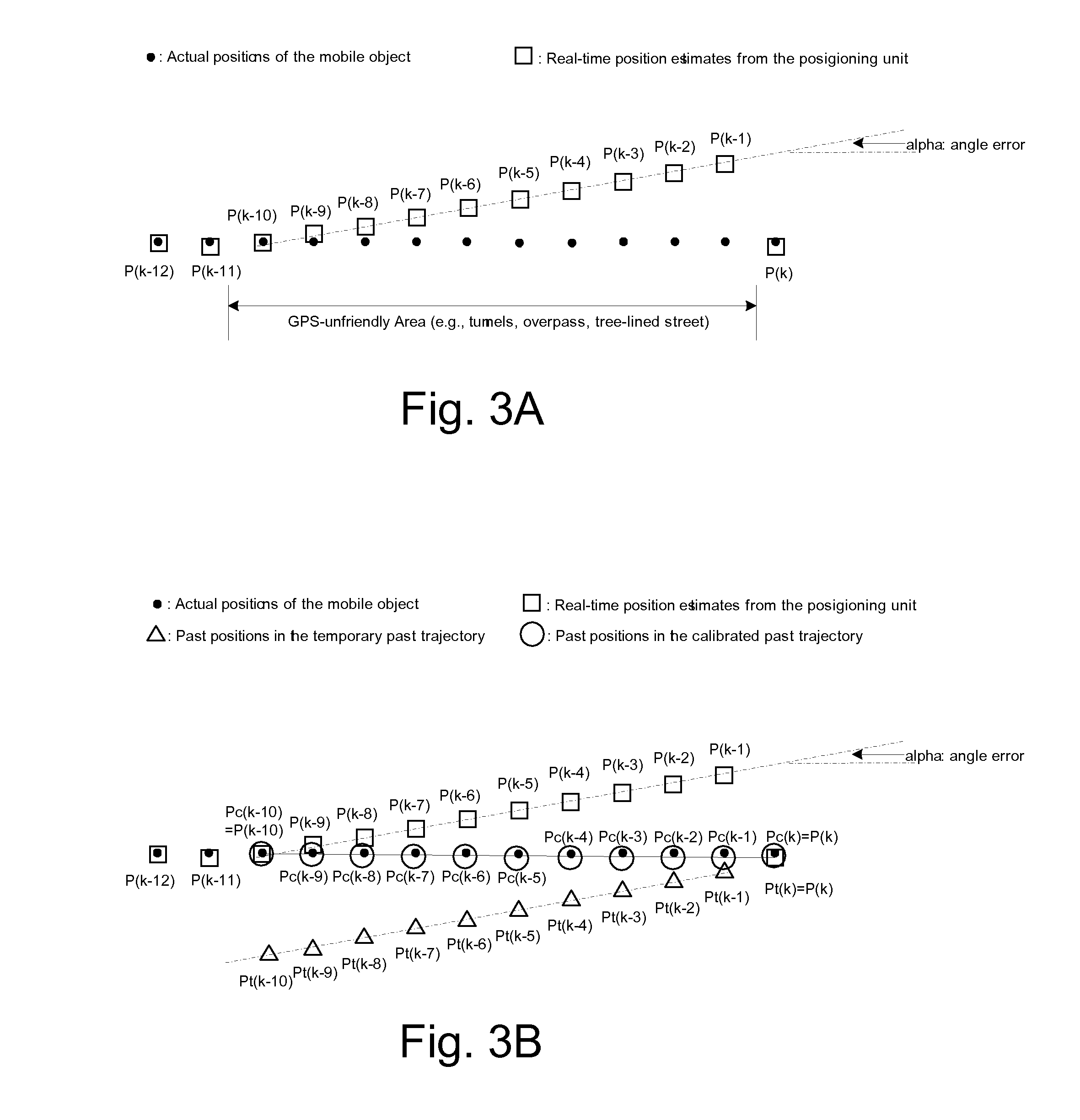
[0066]In a second embodiment with the confidence level available, the combination can incorporate the confidence levels of the position estimates in the first past trajectory. As the temporary past trajectory is generated based on the backward projection model and the most recent position estimate (i.e., Pt(k)=P(k)), the temporary past trajectory has confidence levels associated with P_conf(k) (the confidence level of position estimate P(k)). For example, the confidence level of every temporary past position Pt(i) can be set to be P_conf(k); alternatively, the confidence level of Pt(i) can decrease as (k−i) increases to take into consideration model inaccuracies and uncertainties:

Ptconf(i)=Pconf(k)×γ(k-1), where 0<γ≦1 (e.g. γ=0.95)

[0067]Accordingly, a linear combination of the first past trajectory and the temporary past trajectory can use weighting factors (β(i)) that are functions of both the confidence levels of the first past trajectory and the confidence levels of the second pa...

third embodiment

[0069]In a third embodiment with the confidence level available, the first past trajectory can be further evaluated and portions of first past trajectory can be selected based on its corresponding confidence levels. Take an example where n=Lmin=20 and let's assume that, in the first past trajectory [P(k), P(k−1), . . . , P(i), . . . , P(k−n)], only [P(k), P(k−1)], [P(k−5), P(k−6), P(k−7)], P(k−10), [P(k−14), P(k−15)], and [P(k−19), P(k−20)] have confidence levels higher than a pre-defined threshold. Thus, only these first position estimates are selected to be used in the combination to generate the calibrated past trajectory. That is, if P(i) is among the selected first position estimates, the corresponding position in the calibrated past trajectory, Pc(i) is computed as: Pc(i)=β(i)×P(i)+(1β(i)×Pt(i)); if P(i) is not among the selected first position estimates (that is, P(i) has a confidence level lower than the pre-defined threshold), Pc(i) is simply set to be the Pt(i): Pc(i)=Pt(i...


PUM


Abstract

A method is provided for calibrating past position estimates from a positioning system that provides real-time position estimates of a mobile object. The method first stores the real-time position estimates, which as time goes by become past position estimates and naturally form a first past trajectory depicting the past movement of the mobile object. Subsequently, a calibrated past trajectory is determined, which includes calibrated past position estimates that correspond to the same time instances as the past positions in the first past trajectory. When real-time positions have low qualities, this method calibrates them at a later time by using (higher-quality) real-time positions both before and after them. Errors in the past positions are then corrected based on the calibrated past trajectory. When used with event detectors that indicate inventory transactions, this method can correct position errors associated with inventory events so as to improve the performance of inventory tracking.

Description

CLAIM FOR PRIORITY[0001]This application is a continuation-in-part of application Ser. No. 11 / 478,991 filed on Jun. 29, 2006, entitled “Automatic Past Error Corrections for Location and Inventory Tracking,” which claims priority to U.S. Provisional Application Ser. No. 60 / 696,619 filed Jul. 5, 2005, both of which are incorporated by reference herein in their entirety.BACKGROUND[0002]1. Technical Field[0003]The present invention relates to tracking the location of a mobile object, such as a container that is carried on ships, railroad cars or trucks, or stored in freight yards. The present invention provides an automatic means to correct positioning errors after real-time positions of the mobile object have been reported from a real-time positioning system.[0004]2. Related Art[0005]Position or location tracking is a crucial component of many inventory and resource monitoring and management systems. Typical location tracking systems employ real-time positioning sensors that continuous...

Claims


Application Information

Patent Timeline
IPC IPC(8): G01C21/00
CPCG01C21/165G01S5/0257G01S19/49G01S19/48G01S19/39G01S19/393G01S19/396G01S19/485G01S5/02585
Inventor TAN, HAN-SHUEHUANG, JIHUA
Owner MI JACK PRODS
Why Eureka
Try Eureka